Clear Sky Science · en
Optimizing robot weaving width improves the microstructure and mechanical performance of 4043 aluminum alloy in CMT-WAAM
Building Better Metal Parts with Smart Robot Motion
Additive manufacturing, often called 3D printing, is moving from plastic trinkets to large metal parts for airplanes, cars, and energy systems. This study looks at a very practical question: when a welding robot “weaves” back and forth to build aluminum walls layer by layer, how wide should that weaving motion be to make parts that are strong, reliable, and fast to produce? The answer turns out to be crucial for balancing speed, internal structure, and safety in real-world components.
Why Aluminum Walls Need a New Way to Be Built
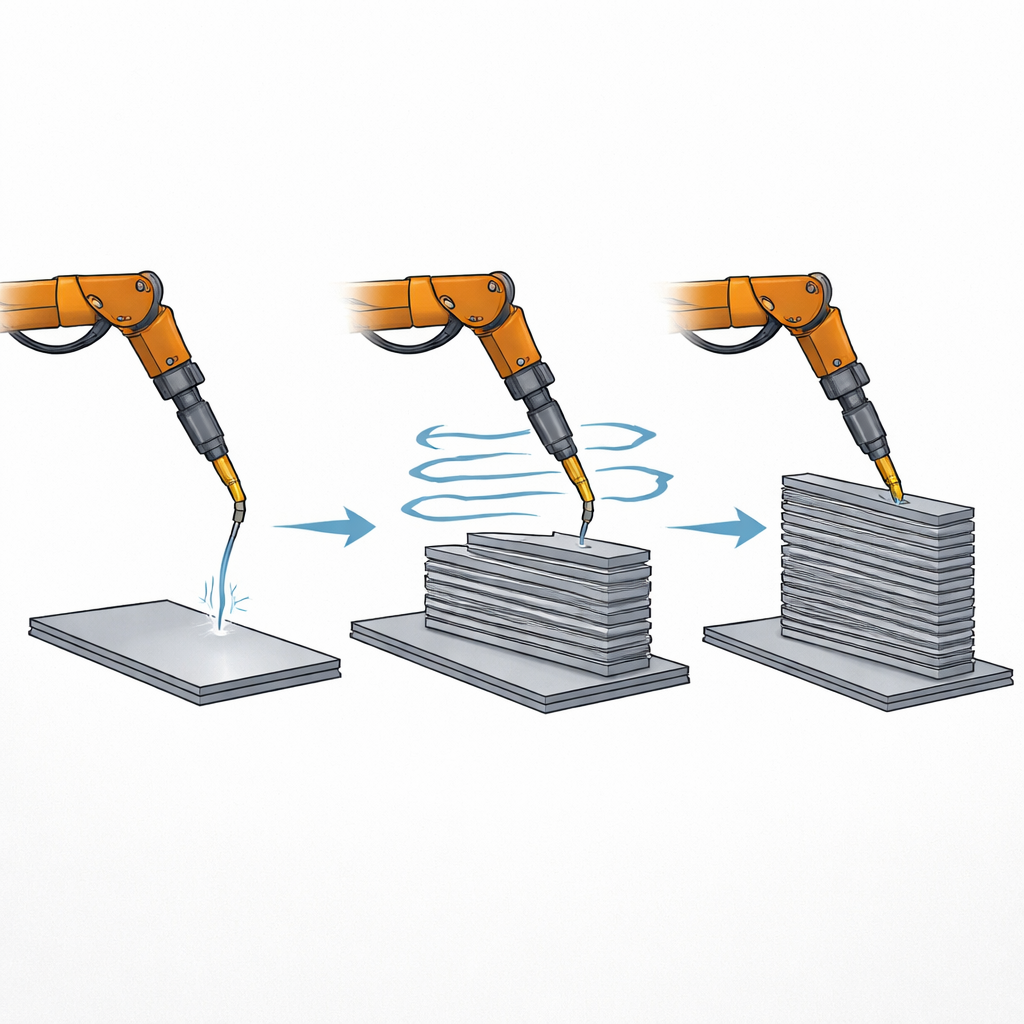
Aluminum alloys are prized because they are light, strong, and resist corrosion, which makes them ideal for aircraft, vehicles, and offshore equipment. Traditional methods like casting and forging struggle when parts need to be both large and intricately shaped, and some laser-based 3D printing techniques have trouble with aluminum’s tendency to reflect light and conduct heat. Wire-arc additive manufacturing offers a different route: a robotic arm feeds a metal wire into an electric arc, laying down molten metal in stacked tracks to form a part. In this work, the team used a gentler version of arc welding called cold metal transfer, which delivers metal with low heat and minimal spatter—well suited to aluminum. They focused on 4043 aluminum alloy, a common, easy-to-process material, and asked how the robot’s side-to-side weaving width affects the finished wall’s internal grain pattern and mechanical performance.
Testing Narrow, Medium, and Wide Robot Paths
The researchers built thin aluminum walls about 20 layers high using three weaving widths: 4 millimeters (narrow), 6 millimeters (medium), and 8 millimeters (wide). Between layers, they carefully controlled temperature, pausing until the wall cooled below 100 °C to keep heat buildup in check. They then cut samples from the top, middle, and bottom of the walls and examined them with optical and electron microscopes, X-ray diffraction, and a technique that maps crystal orientations and grain sizes. They also measured hardness from bottom to top and pulled test bars in both the direction of travel and the vertical build direction to see how strong and ductile the material was, and how much it differed from one direction to the other.
How Weaving Changes the Metal Inside
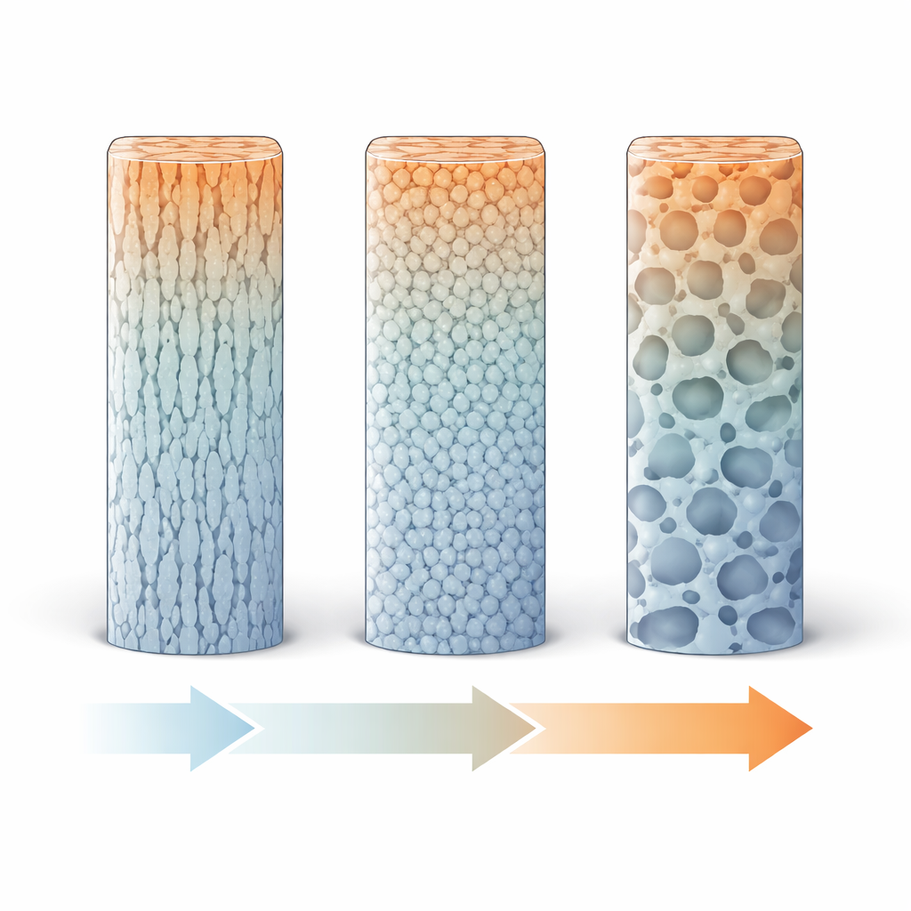
Across all weaving widths, the alloy contained the same basic ingredients: aluminum-rich regions surrounded by silicon-rich channels, arranged in a tree-like (dendritic) pattern. What changed with weaving width was the size and shape of these patterns. A wider weave increases the exposed surface area of each layer, allowing it to cool faster. Moving from 4 to 6 millimeters, this extra cooling refined the internal grains and dendrites, breaking up coarse, plate-like features into a finer mix of shapes that better resist crack growth. Pushing the width further to 8 millimeters refined grains even more, but also encouraged more rounded, globular structures and pores, which are less effective at stopping cracks. Throughout the wall height, the deliberate temperature control kept the structure relatively uniform from bottom to top, unlike many weld-built parts where properties vary strongly with height.
Strength, Stretch, and Directional Balance
When the walls were tested, all three weaving widths produced aluminum with reasonable hardness and ductility, but important differences emerged. The average hardness changed little, yet its variation from bottom to top depended on weaving width, reflecting the changing balance between grain size and hard silicon particles. Tensile tests showed that the medium 6-millimeter weave delivered a particularly attractive combination: good strength and relatively high elongation in both the travel and build directions, along with the smallest difference between those directions. In contrast, the widest 8-millimeter weave reduced ductility, especially vertically, and shifted the fracture behavior toward a mix of ductile and brittle features. The fracture surfaces confirmed this picture: at 4 and 6 millimeters, the metal failed mainly through tiny dimples, a hallmark of ductile tearing, while at 8 millimeters more pores and quasi-cleavage features appeared, signaling a less forgiving material.
What This Means for Real-World Parts
For engineers aiming to 3D print large aluminum components with wire and arc, this work shows that the robot’s weaving width is not just a programming detail—it is a powerful knob that shapes cooling, internal structure, and ultimately performance. A moderate weave of about 6 millimeters offered the best trade-off in this study, boosting build efficiency while preserving strength, ductility, and consistency in different directions. In simple terms, weaving too little or too much can either leave the metal too coarse or introduce harmful features, but an intermediate weave helps the alloy “freeze” into a fine, tough network. Combined with careful temperature control between layers, this provides a practical recipe for building big aluminum parts that are both fast to make and structurally trustworthy.
Citation: Liu, S., Sun, Y., Yuan, X. et al. Optimizing robot weaving width improves the microstructure and mechanical performance of 4043 aluminum alloy in CMT-WAAM. Sci Rep 16, 14005 (2026). https://doi.org/10.1038/s41598-026-43670-x
Keywords: wire arc additive manufacturing, aluminum alloy, robot weaving, cold metal transfer, microstructure