Clear Sky Science · en
Sensitivity-based modeling of error transfer in synchronous cam-linkage mechanisms using a dual-measurement-point approach
Why cam timing matters on the factory floor
Behind many everyday packaged products lies a dance of metal parts that must move in near perfect sync. In packaging machines, cams and linkages lift, grip, and transfer items thousands of times a day. As these parts wear and their original design drawings go missing, keeping motions synchronized becomes difficult, leading to jams, product damage, and costly downtime. This study asks a deceptively simple question: where should engineers measure a worn cam if they want to rebuild it so that the machine runs smoothly again?
How these hidden machine parts do their job
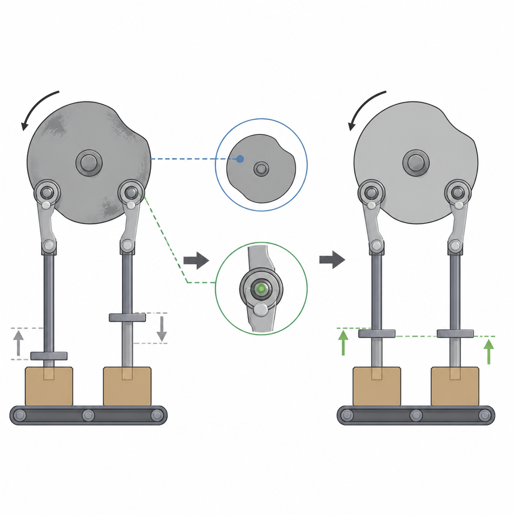
In the system studied, two disk-shaped cams drive a set of arms and grippers that pick up products from one station and place them on the next. As the camshaft turns, small rollers ride on the cam surfaces, causing the arms to swing and the grippers to rise in a straight path. For reliable transfer, the upper and lower grippers must lift together within a tight tolerance. Over years of service, the cam surface wears, its shape becomes irregular, and the once smooth lifting motion turns jerky. When the original blueprints are unavailable, technicians typically scan the worn cam, fit a smooth curve to its inner edge, and machine a replacement. Yet, even with a neat-looking profile, the two grippers can still fall out of step.
Two ways to measure the same motion
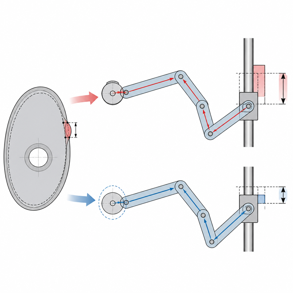
The authors examine two different measurement strategies for rebuilding a worn cam. The traditional method records the inner contour of the cam body and builds a mathematical curve through these points. The alternative proposed in this work measures the motion path of the roller’s center as it rides on the cam. Both sets of data can be used to reconstruct a working cam, but they feed errors into the mechanism in different ways. The team constructs detailed motion models for the full cam-linkage system and tracks how tiny geometric deviations at the cam surface or roller center grow or shrink as they travel through the chain of arms to the final gripper displacement.
Following error as it spreads through the mechanism
To understand how sensitive the system is at each angle of cam rotation, the study defines a sensitivity index: how much the gripper position changes when there is a small radial error at the cam or roller. When errors are defined on the cam’s inner contour, they must first be translated through a complex contact geometry between cam and roller before reaching the linkage. Because curvature changes strongly along the synchronization segment, this mapping is highly uneven. The calculated sensitivity swings by roughly a factor of ten across that region. In contrast, when using the roller center as the reference, the error is applied directly as a simple radial offset and then passed into the linkage model. The resulting sensitivity remains almost flat, with a typical value around 2.17, meaning no large local amplification. The team then fits new cam curves using a constrained least squares method with orthogonal polynomials, ensuring that displacement, speed, and acceleration remain continuous and smooth across all segments.
From virtual models to real machine tests
The researchers compare the two strategies by both simulation and experiment. When looking only at how well the curves match the raw measurement points, the inner contour fit appears slightly better, with a maximum deviation of about 0.06 millimeters compared with 0.09 millimeters for the roller path. However, what really matters is how these differences play out at the gripper. The motion model predicts that the inner-contour-based cam can create follower position errors up to 0.39 millimeters, while the roller-based cam limits this to about 0.15 millimeters. Tests on an actual packaging machine confirm these trends. Using high precision laser sensors, the team records gripper motion at different motor speeds. At a moderate speed of 6 rotations per minute, the cam rebuilt from roller data shows a clearly narrower error band than the one rebuilt from contour data. As the speed increases up to 36 rotations per minute, errors grow for both versions but remain much smaller for the roller-based cam, with the maximum synchronization error cut to 57.2 percent of that seen in the contour-based cam.
What this means for keeping machines in sync
For engineers tasked with keeping aging cam-driven equipment running, the message is clear. When original drawings are lost and a worn cam must be reverse engineered, measuring and fitting the roller center path leads to a more stable and forgiving design than relying on inner contour measurements alone. Even if the numerical fit to the raw data is slightly worse, the downstream motion of the grippers is more accurate, because the key sensitivity patterns are smoother and avoid strong error amplification. Combined with smooth curve reconstruction that respects the continuity of motion, this roller-based surveying method offers a practical recipe for repairing and remanufacturing industrial cams so that synchronized motions stay tight, products remain secure, and production lines keep moving.
Citation: Wang, Q., Deng, B., He, P. et al. Sensitivity-based modeling of error transfer in synchronous cam-linkage mechanisms using a dual-measurement-point approach. Sci Rep 16, 15104 (2026). https://doi.org/10.1038/s41598-026-43989-5
Keywords: cam linkage, machine wear, error propagation, reverse engineering, industrial packaging