Clear Sky Science · en
Research on intelligent assembly method of aero-engine deep-cavity nuts based on torque-angle control
Why tightening hidden engine parts matters
Deep inside a jet engine, out of sight of mechanics, huge nuts clamp spinning parts together so they do not fly apart at thousands of revolutions per minute. Getting the tightness of these fasteners “just right” is critical: too loose and the engine can shake itself to pieces, too tight and expensive parts can crack. This paper explores how to tighten a large nut buried nearly a meter inside an aero‑engine rotor more accurately and efficiently, and describes a new smart tool that can see, think, and adjust as it works.
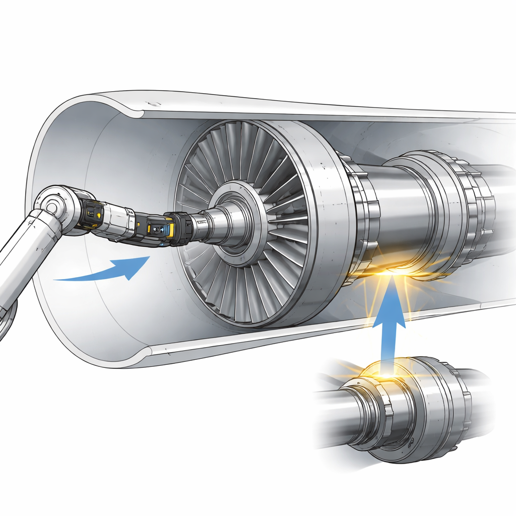
Trouble with hidden heavy-duty fasteners
Modern jet engines rely on threaded connections to hold rotor disks and shafts together while transmitting enormous forces and surviving high temperatures and vibration. One especially tricky task is tightening high‑torque nuts in a deep, narrow cavity of the low‑pressure rotor. Mechanics must achieve torques around two thousand newton‑meters and align locking grooves that prevent the nut from loosening, all without direct line of sight. Traditional methods that rely only on torque measurements are very sensitive to friction and surface condition, often causing large uncertainties in the clamping force that actually holds parts together. Manual alignment inside the cavity is slow, hard to repeat, and risks collisions that can damage costly components.
Looking closely at how surfaces really touch
To understand why clamping force varies so much, the authors first studied the microscopic roughness of the nut and shaft threads. Rather than being smooth, these surfaces look like miniature mountain ranges. The team used a mathematical description of rough, self‑similar surfaces, together with classical contact theory, to model how these tiny peaks squash under load. Their calculations and computer simulations showed that, for typical machined surfaces, only about 12 to 18 percent of the apparent thread area actually makes contact. This patchy contact pattern helps explain why the force produced by a given tightening torque can fluctuate widely, and why models that assume perfectly smooth surfaces overestimate accuracy.
Following the forces through heat and spin
Next, the researchers built a detailed digital model of the nut, shaft, and clamped parts to see how clamping force changes once the engine is hot and spinning. Using finite‑element simulations, they combined mechanical loading, temperature, and centrifugal effects similar to real operating conditions. As the metal heats to several hundred degrees Celsius, it softens and expands, redistributing stress over more threads and reducing the clamping force. At the same time, spinning causes the shaft to grow outward and shorten slightly, further easing the load on the threads. The study found that temperature has the strongest effect, and that together with rotation it can reduce preload by nearly a quarter. Based on these results, the team designed a specific angle “over‑tightening” and preload margin so that, after the engine heats and spins, the remaining clamping force still stays within a safe band.
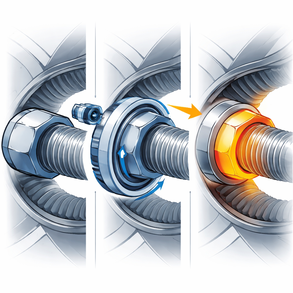
A smart tool that sees and adjusts as it tightens
Armed with this understanding, the authors developed a new deep‑cavity tightening system. It uses a servo‑driven shaft to apply high torque, a miniature camera and inclination sensor to watch the locking grooves, and a computer‑controlled strategy that blends torque and rotation angle feedback. In operation, the tool is guided into the long cavity by specially shaped fixtures that prevent accidental contact with delicate engine parts. It first tightens the nut under torque control until it reaches the target range, then switches to precise angle control to line up the grooves while staying within the allowed torque window. The system continuously records torque, rotation, and predicted clamping force, and can automatically add a small extra turn to compensate for the preload loss expected at high temperature and speed.
Proving the gains in the test stand and workshop
Experiments on representative engine hardware showed that the new approach substantially improves performance. The combined surface and stiffness models predicted overall joint behavior with errors of only a few percent, and the compensation strategy held clamping force within about plus or minus eight percent of the design value even under simulated hot, spinning conditions. In real assembly trials on twenty test engines, the system cut the time needed to tighten each deep‑cavity nut from about four hours to 2.6 hours, reduced preload variation compared with manual methods, achieved angular alignment within roughly a fifth of a degree, and eliminated collision events entirely. In full production use, it has raised assembly pass rates and lowered scrap and rework costs for hundreds of engines.
What this means for safer, smarter engines
For a non‑specialist, the key message is that the authors have turned a difficult, largely manual task into a controlled, data‑driven process. By recognizing that rough surfaces touch only in small patches, that heat and spin steadily relax clamping force, and that seeing and measuring inside a deep cavity is essential, they created a visual, servo‑controlled tightening system that “knows” how tight the nut should be both now and after the engine is running. The result is more reliable joints in critical rotating parts, faster assembly, and fewer costly mistakes—an important step toward more intelligent and trustworthy jet engine manufacturing.
Citation: Liu, Z., Huang, X. & Tan, J. Research on intelligent assembly method of aero-engine deep-cavity nuts based on torque-angle control. Sci Rep 16, 11569 (2026). https://doi.org/10.1038/s41598-026-41867-8
Keywords: aero-engine assembly, threaded joints, torque-angle control, deep-cavity fasteners, visual tightening system