Clear Sky Science · en
Fracture behavior of rod-in-tube layered configurations under three-point bending: an experimental investigation
Why safer metal parts matter
Bridges, aircraft, cranes, and factory machines all rely on metal parts that must not break without warning. Yet real components almost always contain tiny cracks that can suddenly grow and cause catastrophic failure. This study explores a simple way to make common steel rods much more forgiving: by inserting a solid rod inside a matching steel tube, creating a "rod-in-tube" design that can slow crack growth, buy time before breakage, and turn a single sudden failure into a more gradual and detectable process.
How cracks usually bring things down
Traditional design methods often compare the expected loads on a part to how strong the material is when pulled until it yields or snaps. That works reasonably well for flawless pieces of metal, but real structures are full of small flaws, scratches, and internal defects. Around the sharp tip of a tiny crack, stress can become intensely concentrated, so that a part may fracture even when the overall load is well below the metal’s advertised strength. Modern fracture mechanics tackles this problem by focusing on how sharply stress builds up at a crack tip and how easily a crack can advance, rather than just how strong the bulk material is.
A simple layered steel design
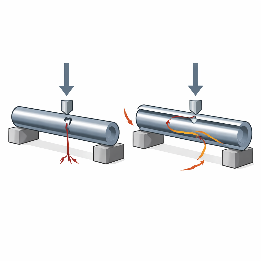
Instead of changing the steel’s recipe or adding complex coatings or adhesives, the researchers tested a purely geometric solution using a widely used medium-carbon steel called EN8. They machined three kinds of specimens, all with the same outer diameter: a plain solid rod, a tube with an 8 mm solid rod press-fitted inside, and a tube with a 6 mm inner rod. Each piece had a small V-shaped notch cut into the outer surface to act as a starter crack. The team then placed these specimens on two supports and pressed down at the center in a classic three-point bending test, recording load, displacement, and time until each sample fractured.
Watching cracks grow in stages
By converting the load and bend data into a measure of crack-driving force, the researchers could track how cracking evolved inside each specimen. The plain solid rod showed a single phase: the crack grew steadily as the bend increased, the crack-driving force climbed to a peak, and the rod failed abruptly. The rod-in-tube samples behaved very differently. They displayed two distinct phases of crack growth. First, the crack moved steadily through the outer tube until it met the interface with the inner rod. At that point, the local driving force stopped rising and even dipped slightly, indicating that the crack was temporarily arrested as load transferred from the outer tube to the inner rod.
Crack arrest and extra time before failure
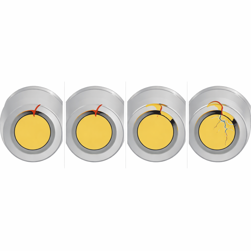
Once the crack reached the interface, the inner rod began to carry more of the load. The crack path changed direction, deflecting along the circular boundary before eventually entering the inner rod. This second stage of growth was slower and more gradual. In time-based plots, the plain rod reached its breaking point after about 18 minutes of loading. The specimen with the thicker inner rod lasted about 45 minutes—an improvement in time to failure of roughly 115%—while the one with the thinner inner rod lasted about 32 minutes, or 50% longer than the plain rod. Although the layered specimens broke at somewhat lower peak crack-driving values than the solid rod, they bent farther, absorbed more energy, and crucially, failed less suddenly.
What the broken pieces reveal
Close inspection of the fracture surfaces supported this picture. The plain rod showed a relatively straight, simple crack path consistent with rapid brittle-like failure. The rod-in-tube samples instead showed three visually distinct zones: a dull region in the outer tube corresponding to stable crack growth, a transition band at the tube–rod interface where the crack deflected and briefly halted, and a final region in the inner rod that combined slow extension with a last sudden break. This stepped pattern is the hallmark of "fail-safe" behavior: the component gives clear warning and survives longer under load instead of snapping without notice.
Design lessons for real structures
To a non-specialist, the key message is that clever geometry can make standard steel parts much more tolerant of damage, without changing the material itself or resorting to complex manufacturing. Simply placing a solid rod inside a tube of the same steel created an internal boundary that forced cracks to bend, slowed their advance, and spread out the stresses. The best-performing design, with a relatively thick inner rod and thinner tube wall, more than doubled the time to failure under bending. For safety-critical hardware—from drive shafts to pins and columns—such rod-in-tube layouts could offer both a longer working life and a gentler, more predictable mode of failure, giving engineers and inspectors valuable time to detect and fix problems before disaster strikes.
Citation: Kumar, M., Londhe, N.V., Ramachandra, C.G. et al. Fracture behavior of rod-in-tube layered configurations under three-point bending: an experimental investigation. Sci Rep 16, 11297 (2026). https://doi.org/10.1038/s41598-026-39990-7
Keywords: fracture mechanics, rod-in-tube, crack arrest, fail-safe design, EN8 steel