Clear Sky Science · en
Single-phase to three-phase DC-link boost converter with reduced controlled switch count
Power from One Wire to Three
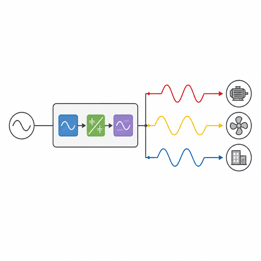
Many homes and small workshops have only a simple two wire wall outlet, while the machines that move water, power factories, and drive electric vehicles often need a stronger three wire supply. This study explores a new electronic circuit that can turn an ordinary single phase power source into a stronger three phase supply using fewer parts, making it easier and cheaper to run heavy duty motors from common outlets.
Why Turning One Phase into Three Matters
Three phase motors run more smoothly and efficiently than those powered by a single line, which is why they are widely used in industry and transport. However, distributing full three phase power to remote farms, small workshops, or isolated stations is costly. Instead of rewiring the grid, engineers often place a converter between the wall socket and the motor. Existing converters can do the job, but they typically require many switches, bulky capacitors, and complex control methods, which raise cost, size, and energy losses.
A Simpler Path from Wall Outlet to Motor
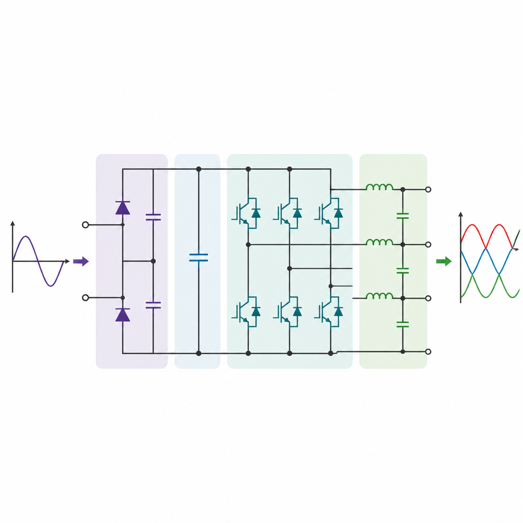
The authors propose a new single phase to three phase converter that also boosts the output voltage above the input level. At its heart are only six controlled switches, two diodes, and two capacitors that form a central energy store called a DC link. The front part of the circuit uses two diodes and split capacitors to turn the incoming alternating power into a steady mid level voltage. The back part uses six switches arranged in three legs to rebuild this steady voltage into three balanced wave like outputs whose strength and frequency can be adjusted for the motor.
How the New Circuit Shapes Clean Power
To control the switches, the design uses a common method called sinusoidal pulse width modulation. In simple terms, it compares smooth reference waves with a fast triangular signal to decide when each switch turns on and off. This timing pattern creates three almost sinusoidal output voltages while keeping the number of switches low. The circuit also includes compact inductor capacitor filters that smooth out remaining ripples, so both the input current from the wall and the output currents to the motor have low distortion and follow power quality limits set by electrical standards.
Testing the Idea in Software and in the Lab
The team first built a detailed mathematical model of the rectifier, the inverter, and the filter, then simulated the system using MATLAB/Simulink. With an 80 volt input, the converter produced about 160 volts per phase, showing a voltage gain of two while keeping input current distortion around 6.85 percent and output current distortion around 0.37 percent. Changing the input to 60 volts and the load to a higher resistance still yielded roughly 160 volts per phase, raising the voltage gain to about 2.7. They then built a hardware prototype using insulated gate bipolar transistors and a digital control board, and measured waveforms, current spectra, and switch voltages. The lab results closely matched the simulations and showed converter efficiency between 85 and 90 percent, with each switch seeing only moderate voltage stress.
What This Means for Real World Use
For readers, the key message is that the new converter can turn a modest single phase supply into a stronger, cleaner three phase source using fewer electronic parts. This helps keep costs, size, and heat losses down while still delivering smooth power that motors like. In practice, such a design could make it easier to run three phase equipment in places that only have access to standard outlets, without sacrificing efficiency or power quality.
Citation: Nagi, H.A., El-Sabbe, A.E. & Osheba, D.S.M. Single-phase to three-phase DC-link boost converter with reduced controlled switch count. Sci Rep 16, 16146 (2026). https://doi.org/10.1038/s41598-026-53542-z
Keywords: single phase to three phase converter, power electronics, voltage boost, motor drives, harmonic distortion