Clear Sky Science · en
Calibration of impulse high-voltage test systems above 500 kV peak: implementation and evaluation
Why pushing voltage tests higher matters
Modern power grids, electric trains, and long-distance cables all rely on equipment that must survive sudden spikes of electricity, much like a building must withstand an earthquake. These spikes, called impulse voltages, can reach hundreds of thousands of volts and are used in laboratories to mimic lightning strikes or abrupt switching events. As industry builds test systems that reach ever higher voltages, a practical problem has emerged: how do you reliably check that these giant test rigs are actually producing the voltages they claim, especially when portable reference devices cannot reach those extremes? This study tackles that metrology challenge head-on.
Electric shocks by design
High-voltage impulse tests are intentionally harsh electrical “shocks” applied to power cables, transformers, insulators, and other grid components to see whether they will fail under real-world stress. In the lab, a special generator rapidly charges a stack of capacitors and then discharges them in a single, sharp pulse, imitating a lightning bolt or a switching surge. Test standards define key features of this pulse: how high the voltage peaks, how fast it rises, and how long it takes to decay. Because the voltages can reach hundreds of kilovolts, engineers cannot measure them directly. Instead, they use tall voltage dividers that safely scale the impulse down to a small signal, which is then recorded by a digital instrument.
The calibration bottleneck
To trust any measurement, the equipment must be periodically calibrated against a reference. National metrology institutes typically send portable reference systems that can handle impulse voltages up to about 500 kilovolts. However, many industrial test systems now exceed this level, reaching 800 kilovolts and beyond in cable factories and high-voltage laboratories. Physically moving these huge test installations to a national lab is impractical, and the available on-site reference systems cannot be pushed beyond their safe limit without risking damage. As a result, the upper part of the test system’s range has often remained unverified, even though it is exactly the range needed for advanced grid equipment.
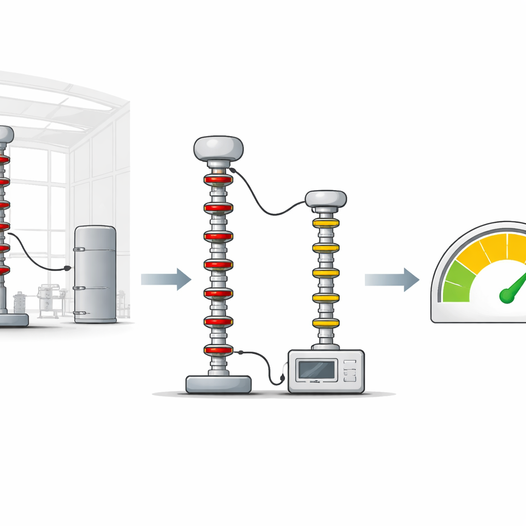
A clever shortcut using charging voltage
This work presents a way to bridge that gap using information that is already present in the test setup: the direct-current (DC) voltage used to charge the impulse generator. Alongside a standard 500 kilovolt impulse divider, the author uses a precise DC divider that measures the charging voltage feeding the multi-stage generator. Within the safe 500 kilovolt range, the study measures, point by point, both the actual impulse peak (using the standard divider) and the DC charging voltage. From these paired measurements, it extracts an “efficiency factor” that describes how effectively the generator converts its DC charge into an impulse peak. If this factor stays nearly constant across the calibrated range, it reveals a stable, linear behavior that can be used as a scale factor.
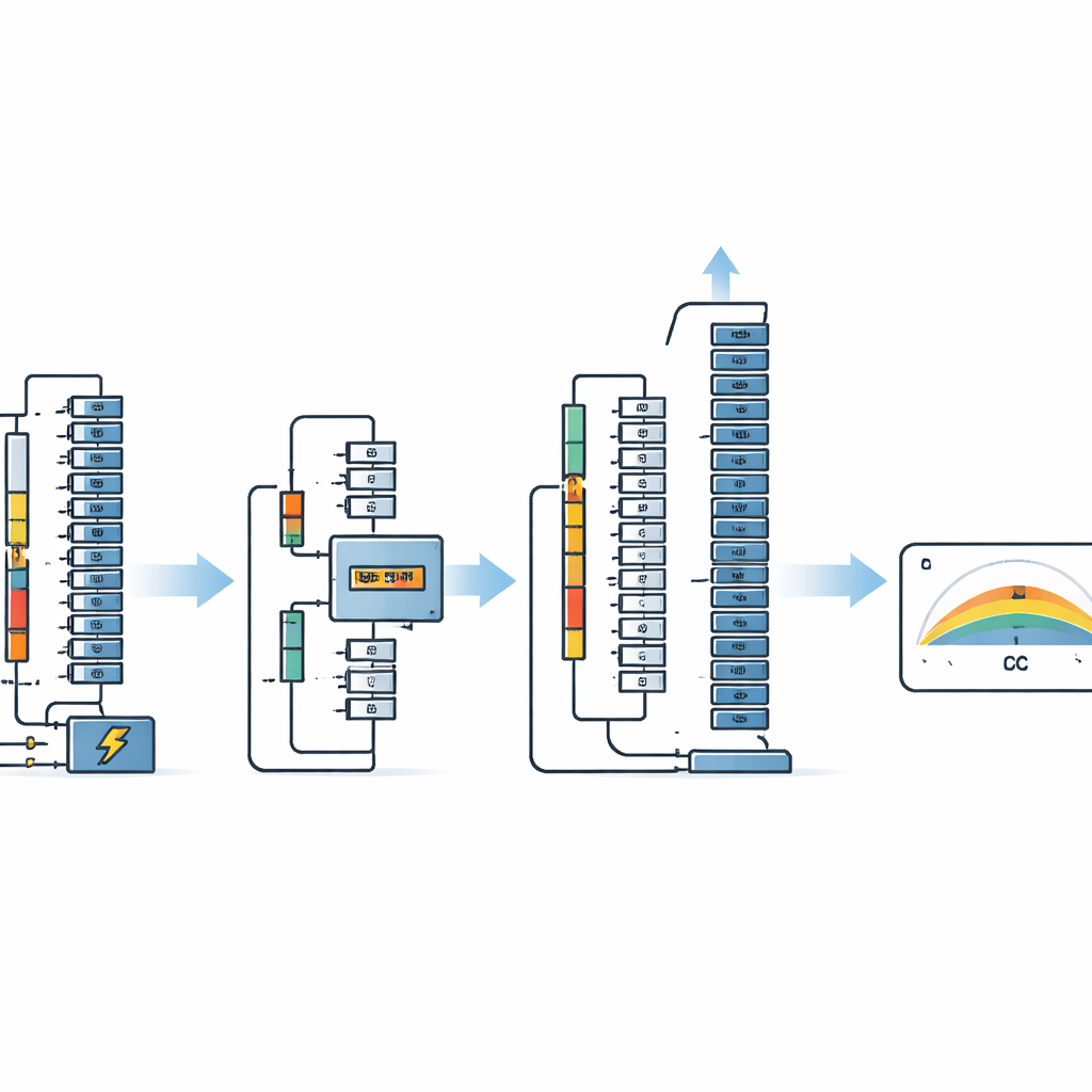
Extending trust to higher voltages
Once the efficiency factor is established and shown to vary by less than about one percent, the reference impulse divider is removed for safety, and the test system is driven to higher voltages—600, 700, and 800 kilovolts. At these levels, only the DC charging voltage and the unit-under-test divider are active. The measured DC voltage, multiplied by the previously determined efficiency factor and the number of generator stages, provides an estimated “reference” impulse value against which the unit-under-test can be checked. Detailed uncertainty calculations, following international guidance, show that the total uncertainty remains comfortably below the three percent limit required by the relevant standards for peak impulse measurements, both within and above the 500 kilovolt range.
Checking the method and looking ahead
To be sure the new approach is sound, the author compares the extended-range results with an earlier calibration of the same system from a specialized high-voltage laboratory in Germany. Using a statistical tool called normalized error, which weighs both the differences in measured values and their stated uncertainties, all comparison points fall within the accepted bounds. This indicates that the new on-site method is consistent with a much more demanding laboratory calibration, even up to 800 kilovolts. The paper also discusses limits of the approach, noting that environmental conditions, subtle changes in spark gaps, and long-term aging could influence the efficiency factor and deserve further study.
What this means in practice
In everyday terms, this research shows how to use a well-understood part of the test system—the charging voltage—as a reliable yardstick to extend calibration far beyond the nominal reach of portable reference equipment. By proving that the relationship between charging voltage and impulse peak stays essentially straight and predictable, the author demonstrates that engineers can confidently verify impulse tests up to 800 kilovolts (and potentially higher voltages) without needing massive new standards hardware. This makes it easier for factories and high-voltage labs to prove that their “artificial lightning” is as strong and well-measured as they claim, helping ensure that the grid equipment we depend on is tested safely and accurately.
Citation: Haiba, A.S. Calibration of impulse high-voltage test systems above 500 kV peak: implementation and evaluation. Sci Rep 16, 14149 (2026). https://doi.org/10.1038/s41598-026-50002-6
Keywords: high-voltage calibration, impulse testing, voltage divider, measurement uncertainty, power grid reliability