Clear Sky Science · en
Near-field imaging of buried conductors using transient EM signal transfer
Seeing What Lies Beneath
Many important objects are hidden just below the surface of the ground, from buried power cables and steel bars in bridges to unexploded shells left from past conflicts. Finding these conductors safely and cheaply without digging is a long-standing challenge. This study introduces a new way to “see” such buried metal shapes using brief bursts of electromagnetic energy and a simple handheld antenna setup, turning tiny changes in electrical behavior into clear pictures of what is underground. 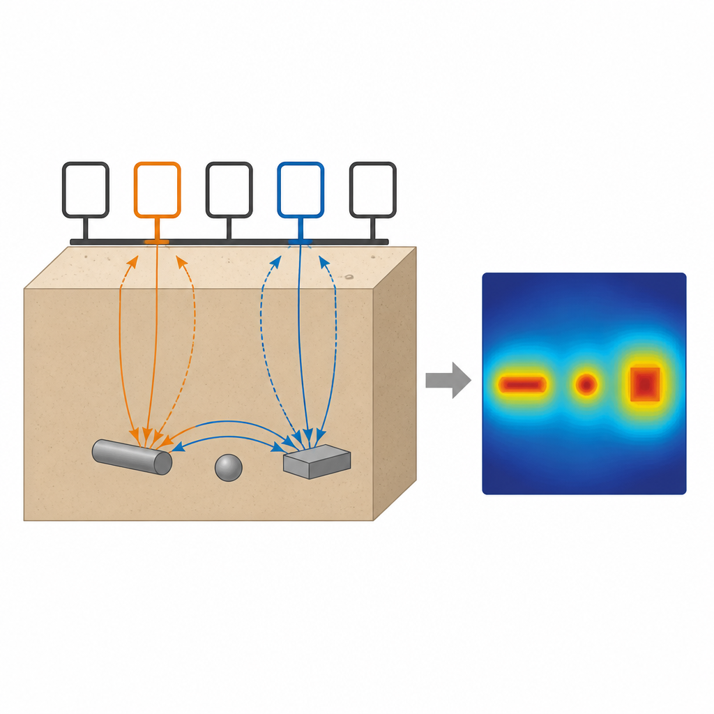
A New Way to Look Underground
Scientists and engineers have long used electromagnetic tools to explore what we cannot see, including the search for underground water, unsafe structures, and even tumors inside the body. Classic systems either listen at fixed radio frequencies or send out pulses and watch how the signal fades over time. These approaches can be powerful but often need complicated hardware, long scans, and heavy data processing. The new method in this paper focuses purely on very short time pulses and how they pass between two small loop antennas placed on the surface, offering a simpler and more flexible option.
Listening to Tiny Conductivity Clues
The core idea is to measure how easily electrical currents can move in the ground below the antennas. When a sharp current pulse is sent into a transmitting loop, it creates a rapidly changing electromagnetic field that seeps into the soil. A receiving loop nearby picks up a voltage signal that depends on how conductive the underground material is. The authors compare the measured signal with a mathematical model that predicts the response for different conductivities. By finding the best match, they estimate an “effective conductivity” beneath the pair of loops, which captures the average contrast between the background soil and any buried metal object, rather than the exact material value itself.
Stamping Out an Underground Picture
To turn these local conductivity readings into an image, the researchers designed a compact array of five loops: one in the center sending pulses and four around it receiving signals. Placed on the ground, this array effectively samples a three-by-three patch beneath it. The same array is then rotated by 45 degrees and used again, like taking a second “stamp” of measurements from a new angle. For each position, the team first records a reference conductivity with no object present, then repeats the measurement with a metal target buried in sand. The difference between the two is converted into a “probability” map that shows where a buried object is likely to be, and the two maps from different angles are averaged and smoothed to form a continuous picture. 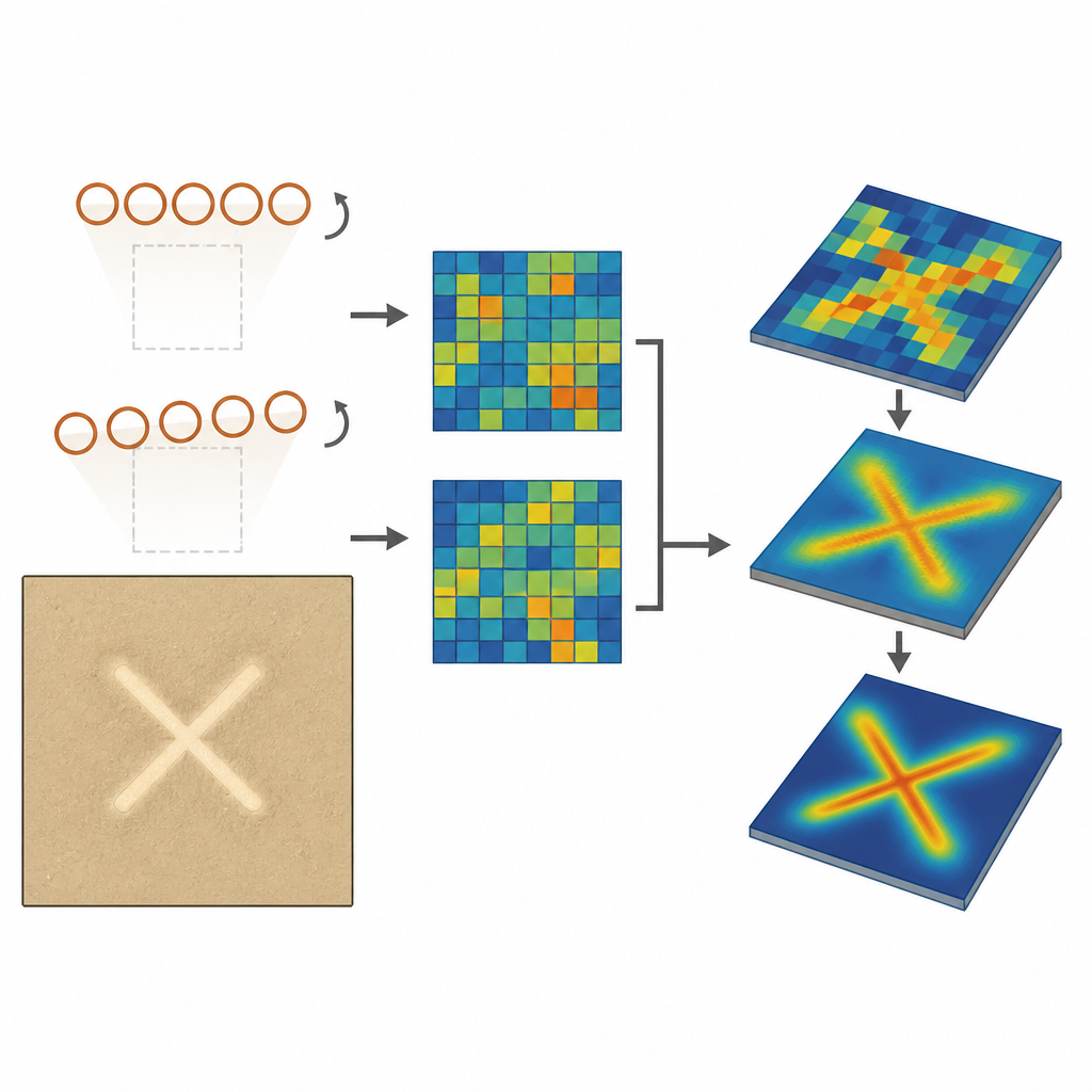
Sharpening Edges and Testing Shapes
Because the raw maps are coarse and blocky, the authors apply image-processing steps commonly used in computer vision. They upscale the grid to a fine pixel map and smooth it with Gaussian filters, then use thresholding to mark likely object regions and special shape operations to refine edges and trace outlines. To test how well this works, they buried metal tubes arranged in three different shapes, labeled X, Y, and Z, just 5 millimeters under a layer of silica sand. Across all cases, the reconstructed maps closely resembled the true outlines: the central axes of the shapes lined up well with the original objects, while the apparent thickness was slightly broadened, as expected from the averaging nature of the measurement.
How Deep and How Precise
The team further explored how the method behaves as objects are buried deeper and moved sideways relative to the antennas. As the depth increased up to about 3 centimeters, the contrast in effective conductivity steadily weakened and approached the background value, but still remained measurable for moderate depths. When the object was slid laterally, the strongest response occurred when it lay roughly between the two loops, and faded smoothly as it moved away. These trends match physical expectations and help define practical limits for real-world use, such as how finely one must scan and how close the sensor needs to be to a target.
Why This Matters
To a non-specialist, the key message is that the authors have shown a lean, low-cost way to locate and outline buried metal using only two quick measurements from a small loop array and modest calculations. Instead of relying on heavy equipment or complex multi-frequency systems, this approach turns subtle differences in how a short pulse travels between two coils into clear maps of underground conductors. With further refinement and more scan positions, it could become a useful tool for tasks like checking building foundations, surveying near-surface geology, or screening for unexploded shells, all without digging or disturbing what lies below.
Citation: Doležal, T., Štumpf, M. Near-field imaging of buried conductors using transient EM signal transfer. Sci Rep 16, 15853 (2026). https://doi.org/10.1038/s41598-026-46396-y
Keywords: buried conductors, electromagnetic imaging, time-domain EM, subsurface detection, loop antennas