Clear Sky Science · en
Influence of connection configuration on the punching resistance of CFST column–RC slab systems under eccentric loading
Why safer building joints matter
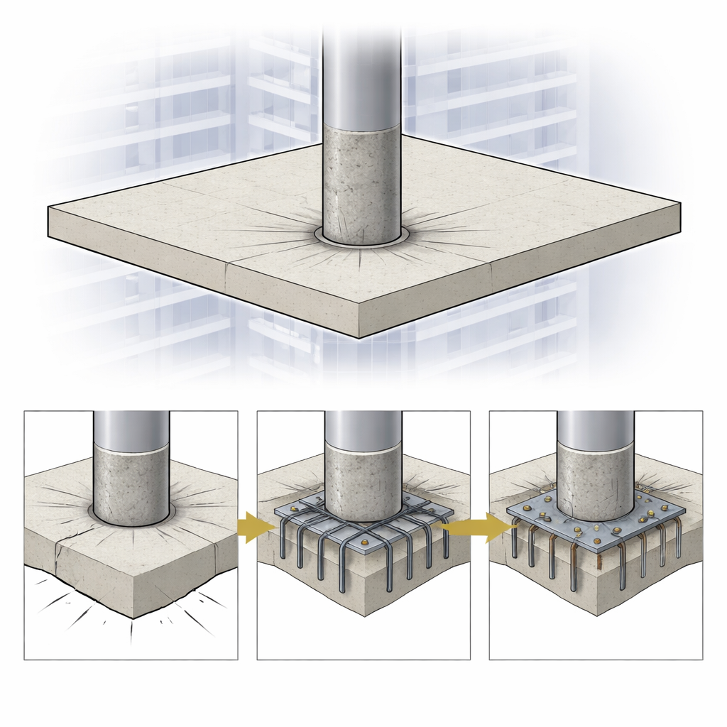
In modern cities, high‑rise buildings increasingly rely on flat, beam‑free floors supported directly by sturdy columns. This clean look frees up interior space but hides a vulnerable spot: the small area where each column meets the floor slab. If that joint fails suddenly, the floor can "punch" around the column and collapse locally. This paper explores how to make that hidden joint much tougher and more forgiving, using smart steel details that can be built in from the start rather than added later as repairs.
Blending steel tubes and flat floors
The study focuses on a popular hybrid system: concrete‑filled steel tube (CFST) columns connected to reinforced concrete flat slabs. In these columns, a hollow steel tube is packed with concrete, combining the strength and stiffness of both materials. Flat slabs rest directly on the columns without deep beams, which saves height and makes layouts flexible. The downside is that loads from upper floors are funneled through a small slab area around each column. When the load is offset from the column center – for example due to uneven use of space or earthquake forces – the slab can crack and fail in a brittle "punching" mode unless the joint is carefully detailed.
Testing different ways to tie slab and column together
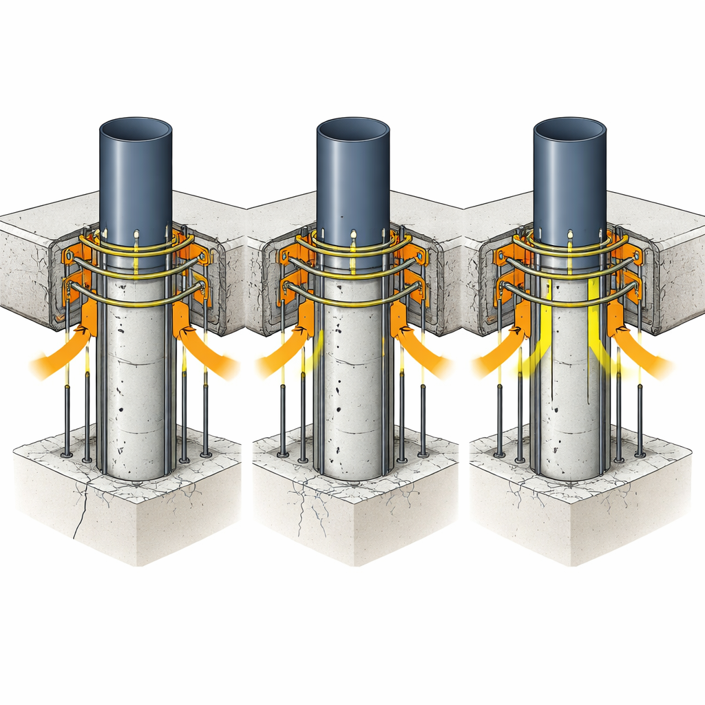
To understand which details work best, the researchers built and tested twelve slab‑and‑column specimens in the lab. Each specimen used the same size slab and CFST column, but the way they were connected varied. Some had no special preparation at all, serving as a control. Others used steel bars welded around the outside of the tube, short or long bolts glued into the tube wall and anchored into the slab, or C‑shaped bars hooked around the tube and embedded in the concrete. Several specimens combined these ideas, such as two rows of welded bars plus four deeply anchored bolts, or C‑shaped bars with different embedment lengths. All slabs were loaded near, but not exactly at, the column center to reproduce realistic eccentric loading.
Watching cracks, strength, and flexibility
During testing, the team measured how much each slab deflected, recorded when the first visible cracks appeared, tracked crack patterns, and pushed the specimens all the way to failure. The plain connection performed worst: it cracked at a low load and failed suddenly as the column punched through the slab. Adding even a single row of welded bars significantly raised both the cracking load and the ultimate capacity, and changed the failure from brittle punching to a more gradual bending‑plus‑punching behavior. Using two welded rows was even more effective, especially when the main slab reinforcement was placed close to those welded bars so they worked together to share the load.
Bolts, bar layouts, and C‑shaped connectors
Bolted connections also improved joint behavior, but their effectiveness depended strongly on how deeply the bolts were anchored into the slab. Increasing embedment length from a shallow 16 mm to 48 mm nearly tripled the ultimate capacity and made the load‑deflection response more ductile, meaning the joint could deform more before failing. Fine‑tuning the reinforcement layout around long bolts brought further gains: a steel mesh or an extra upper reinforcement layer helped spread stresses and control cracks much better than simply spreading bars widely. Among all tested details, C‑shaped bars with a generous embedded length performed exceptionally well, providing high strength, stiffness, and energy absorption while keeping crack patterns more uniform.
The best mix of details
The clear standouts were hybrid systems that combined different connection devices so they could share the task of carrying load. A joint using two welded rows of larger‑diameter bars plus four deeply embedded bolts reached the highest capacity among welded solutions and showed very gradual softening after peak load, a sign of excellent toughness. The longest C‑shaped connectors delivered similarly impressive strength with large deformations before failure. Across all specimens, the most influential factors were the basic connection type, followed by how deeply mechanical anchors were embedded, with reinforcement arrangement acting as a valuable fine‑tuning tool.
What this means for real buildings
For non‑specialists, the key message is that the way we tie steel columns into flat concrete floors can make the difference between a sudden, brittle failure and a joint that cracks gently and keeps carrying load. By designing in welded bars, properly anchored bolts, or C‑shaped connectors from the outset – and placing the surrounding reinforcement to work with them – engineers can greatly raise the load levels that joints can handle and give structures more warning and reserve strength before failure. This makes CFST column–slab systems not only efficient and architecturally flexible, but also safer and more resilient under the uneven and changing loads that real buildings experience.
Citation: Ghalla, M., Bazuhair, R.W., Mahfouz, Y.M.B. et al. Influence of connection configuration on the punching resistance of CFST column–RC slab systems under eccentric loading. Sci Rep 16, 12475 (2026). https://doi.org/10.1038/s41598-026-46159-9
Keywords: concrete-filled steel tube columns, flat slab punching shear, slab-column connections, eccentric loading, connection detailing