Clear Sky Science · en
Development and testing of a high-precision static calibration device for aviation thin-film thermocouples
Measuring Heat Where It Matters
Modern jet engines and other high‑temperature machines run so hot that only tiny, fast sensors can survive on their surfaces. Thin‑film thermocouples are some of the few devices that can accurately track these extreme temperatures, but they themselves must first be checked and calibrated very precisely. This paper describes a new piece of laboratory equipment that creates an exceptionally stable temperature environment, allowing engineers to trust the readings from these fragile but vital sensors.
Why Tiny Temperature Sensors Need Careful Checking
Thin‑film thermocouples are hair‑thin metal coatings printed directly onto parts such as turbine blades, combustion chambers, and gun barrels. When one end of the film is hot and the other is cooler, an electric signal is generated that reveals the temperature. To turn that signal into a reliable reading, researchers must expose the film to well‑known temperatures and see how it responds. This sounds simple, but in practice it is difficult: many existing calibration furnaces do not keep the heat uniform over the small region where the sensor sits, and the cooler “reference” end can drift as room conditions change. The result is avoidable error in measurements that are used to design and safeguard critical aerospace hardware.
Building a More Even Heat Bath
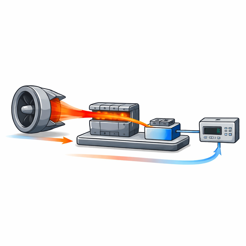
The authors designed a new static calibration device that tackles these weaknesses head‑on. At its heart is a compact tube furnace divided into three heating zones along its length, paired with a separate temperature‑controlled metal block that serves as the cool reference end. A thin‑film thermocouple under test is threaded so that its hot end lies in the middle of the furnace while its cold end rests on the metal block. A highly sensitive electrical meter records the tiny voltage the film produces as the furnace temperature is changed. By carefully shaping how heat is added and removed in both the furnace and the block, the system keeps temperatures steady and uniform, which is exactly what accurate calibration demands.
Shaping Heat with Computer Models
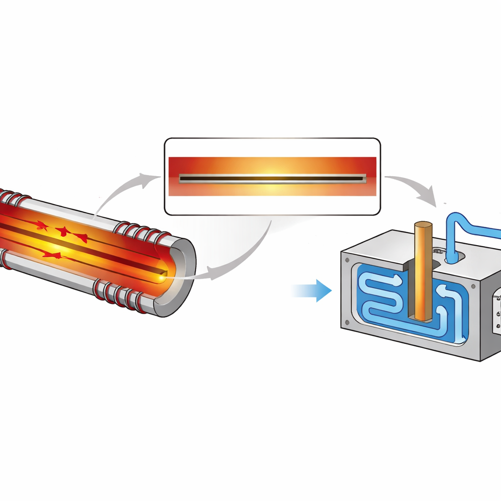
To find the best design before building hardware, the team used computer simulations of heat flow inside the furnace tube and the reference block. In the furnace, they explored different ways of splitting the heating wire into three zones and assigning power to each zone. The goal was a long stretch in the center where the temperature barely changed from point to point. Simulations showed that using equal‑length zones and slightly boosting the power at the two ends flattened the temperature profile without creating hot spots away from the center. For the reference block, the researchers modeled a copper column and top plate heated from below by a rod and cooled by water circulating through a radiator and fan. The balance of heating and cooling produced a nearly uniform temperature across the top surface where the sensor’s cold end sits.
Putting the New Device to the Test
After the simulations, the team built a prototype and compared its performance with a conventional single‑zone furnace. They placed standard, high‑quality thermocouples along the tube to map the temperature every 10 millimeters. In the new multi‑zone furnace, the hottest point lined up with the geometric center, the temperature changed only slightly along the length, and the region of nearly constant temperature stretched to about 100 millimeters. The traditional furnace met minimum national standards but showed a shorter uniform region, a steeper temperature change, and a slight shift of the hottest point away from the center. The reference block also performed well: across its working range of 50–300 °C, its temperature wobbled by less than a quarter of a degree over ten minutes, despite environmental influences.
What This Means for Real‑World Measurements
To confirm that these gains translate into trustworthy numbers, the authors examined how the remaining small variations in temperature and electronics contribute to overall uncertainty. They found that the combined error of the system stays comfortably below one‑third of the allowed tolerance for standard high‑grade thermocouples, a common benchmark in metrology. In plain terms, the new calibration device creates an unusually even and stable pocket of heat on the hot side and a rock‑steady cool side, both of which are needed to “teach” thin‑film thermocouples exactly what different temperatures look like electrically. For engineers designing engines, weapons, or spacecraft components that run on the edge of what materials can tolerate, this means more confidence that the heat maps they rely on truly reflect reality.
Citation: Yang, J., Fang, C., Xu, Z. et al. Development and testing of a high-precision static calibration device for aviation thin-film thermocouples. Sci Rep 16, 10813 (2026). https://doi.org/10.1038/s41598-026-45689-6
Keywords: thin-film thermocouple, temperature calibration, high-temperature furnace, aviation sensors, temperature uniformity