Clear Sky Science · en
Investigation of deformation characteristics of gate and earth–rock dam systems under deep overburden conditions
Why the Shape of a Dam Matters
As countries harness more hydropower, engineers are building dams in places where the ground is anything but simple. In western China, for example, rivers often flow over very thick layers of loose soil and rock before reaching solid bedrock. In these settings, modern projects combine rigid concrete gates with more flexible earth‑rock embankments in a single dam system. This study asks a deceptively simple question with big safety implications: how does such a mixed dam actually deform in three dimensions as it is built and filled with water, and where are the hidden weak spots?
Building a Digital Twin of a Complex Dam
The researchers started by creating a detailed three‑dimensional computer model of a real hydropower project that joins a concrete gate dam to a concrete‑faced rockfill embankment. The model faithfully includes the gate piers and chambers, the rockfill body, underground cutoff and continuous walls, gravity retaining walls, and the thick, uneven blanket of soil and rock—known as deep overburden—resting on the bedrock below. Instead of using a uniform, coarse numerical grid, they adopted an “octree” mesh that automatically refines the grid where the geometry is intricate or stresses are expected to concentrate. Standard elements are handled by a classic finite‑element method, while oddly shaped elements near geometric transitions are solved with a complementary technique called the scaled boundary finite‑element method. This coupled approach lets them capture fine structural details without overwhelming computing resources. 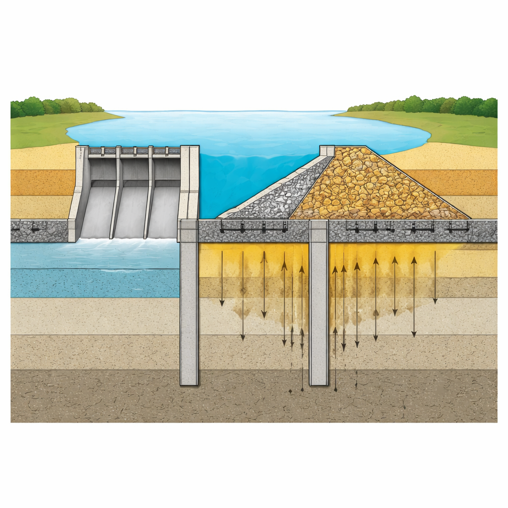
Following the Dam from Construction to Full Reservoir
To mimic reality, the team did not simply apply water pressure to a finished dam. They simulated 32 separate stages: the initial stress in the ground, staged construction of gravity walls, cutoff walls, the gate dam and rockfill embankment, then placement of facing slabs and other components, and finally the gradual rise of the reservoir from riverbed to normal operating level. Each step let the ground and structures settle under their own weight before the next load was added. Concrete parts were treated as elastic, while the soils and rockfill followed an advanced plasticity model calibrated against laboratory tests. This setup allowed the model to reproduce not only how much the dam settles, but also how the surrounding ground yields and redistributes stress as loads evolve over time.
Where the Dam Settles and Where It Stretches
The simulations show that the dam system does not move as a single solid block. The more flexible earth‑rock part settles about 28 percent more than the stiffer concrete gate section. This difference is driven by the larger volume and lower stiffness of the rockfill, as well as a thicker, more compressible overburden layer beneath it. As a result, joints between gate chambers near the banks experience larger shear and opening movements than those in the central region, though predicted displacements remain within current design limits. Another key finding concerns the vertical cutoff wall, which hangs in the overburden instead of being anchored into bedrock. Uneven settlement—greater in the river’s middle than near the banks—causes the wall to bend, creating a zone of significant tensile stress at the top of the right‑bank section. Similarly, underground continuous walls beneath the gravity retaining structures show uneven settlement and rotation, with tension developing both at their bottoms (where vertical deformation is greatest) and near their tops, where the walls are locked to overlying concrete. 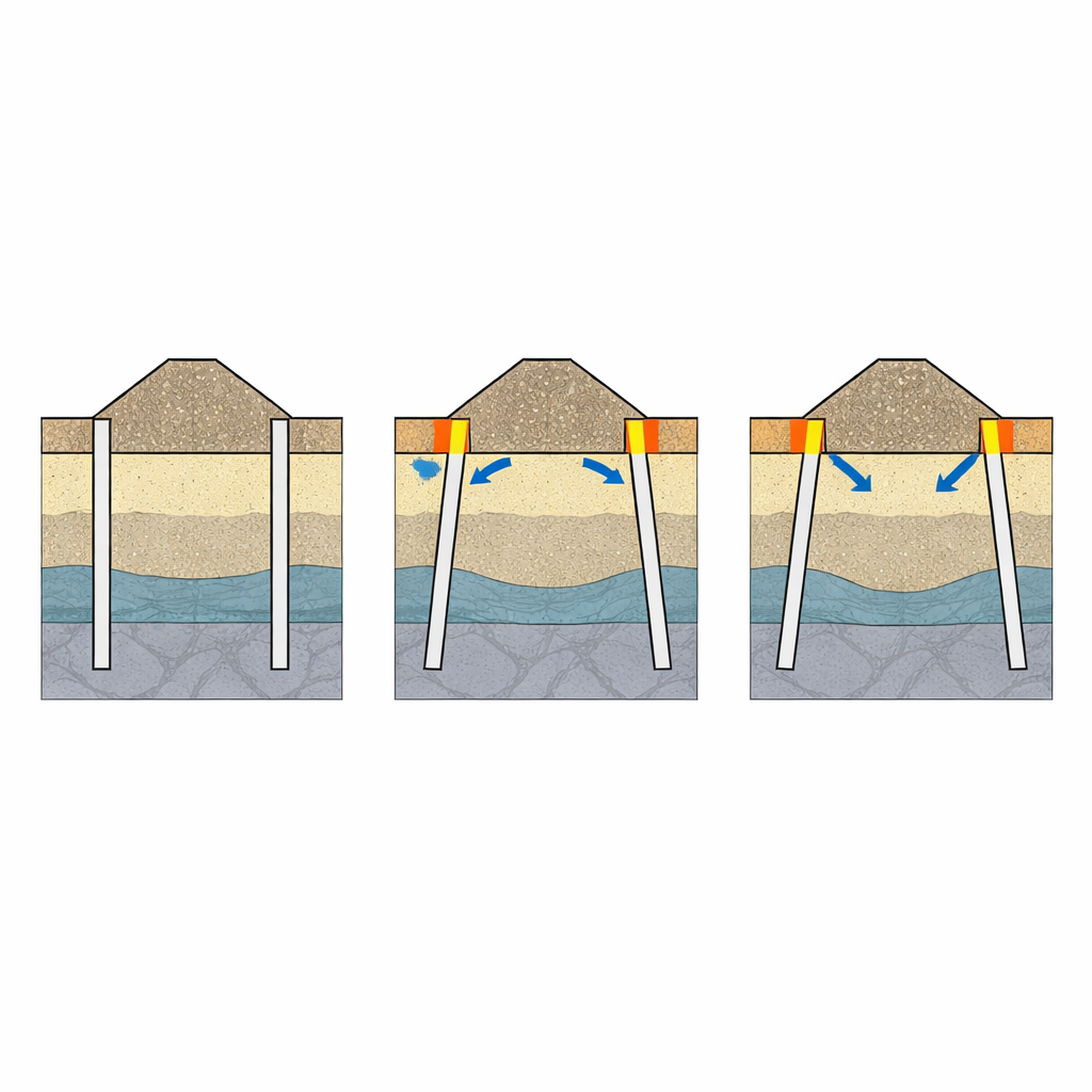
Turning Calculations into Safer Designs
Beyond mapping how this particular dam deforms, the work highlights specific locations that deserve extra attention in design and construction. These include joints between gate chambers, the tops of cutoff walls where bending can induce cracking, and the bases and tops of underground continuous walls where tension can accumulate. Because the predicted settlements are smaller than those observed in some comparable dams, the study also helps place the project’s behavior in context. More broadly, the researchers show that their octree‑based, coupled numerical method can handle large, irregular dam–foundation systems with strong nonlinear soil behavior. They argue that this framework can guide future optimization of reinforcement zones and construction schemes, and can be extended to simulate how such dams might respond to earthquakes, liquefaction of weak layers, and long‑term concrete damage—ultimately contributing to safer hydropower development on challenging foundations.
What This Means for Future Dams
For non‑specialists, the main message is that the safety of a modern dam depends as much on the hidden ground and buried walls beneath the waterline as on the visible concrete crest. By carefully modeling how every part of a mixed concrete and earth‑rock dam deforms together, this study pinpoints where cracks or excessive movement are most likely to start. The approach offers engineers a powerful “x‑ray” of complex dam systems built on deep, soft foundations, helping them strengthen vulnerable zones before problems arise and supporting more reliable, low‑impact hydropower in difficult terrain.
Citation: Liu, B., Wang, F., Zou, D. et al. Investigation of deformation characteristics of gate and earth–rock dam systems under deep overburden conditions. Sci Rep 16, 13464 (2026). https://doi.org/10.1038/s41598-026-44128-w
Keywords: earth-rock dam, deep overburden, finite element modeling, cutoff wall deformation, hydropower safety