Clear Sky Science · en
Isogeometric analysis of wing structures using multipatch parametrization and penalty-based coupling method
Why Wing Structures Matter
Modern airliners rely on wings that are both light and incredibly strong. Designing these wings is a balancing act: engineers must juggle sleek shapes for fuel-saving aerodynamics with internal structures that can safely carry heavy loads. This paper presents a new way to build digital wing models that stay faithful to the designer’s shapes while allowing highly accurate virtual stress tests. The result is a more direct bridge between the drawing board and computer simulation, promising faster and more reliable wing design.
From Curves on a Screen to a Full Wing
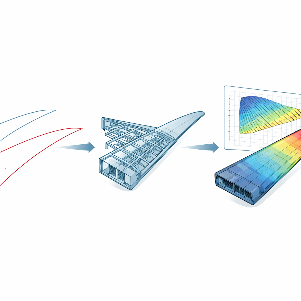
The authors focus on a common challenge in aerospace: how to turn smooth computer-aided design (CAD) shapes into models that can be analyzed without losing detail or adding weeks of mesh-cleanup work. They use a mathematical technology called NURBS, widely used in CAD to describe smooth curves and surfaces, to represent every part of a wing: the outer airfoil shape, the skins, and the interior ribs and spars that form the “wingbox.” Instead of redrawing or simplifying the shapes for analysis, they fit these curves very precisely to airfoil data from standard databases and then build up surfaces and volumes directly from them. This keeps the geometry exactly as the designer intended, down to wind-tunnel level tolerances in the airfoil profiles.
Building the Skin and the Skeleton
Starting from a baseline wing known as the RAE benchmark wing, the team constructs the outer skins by stretching airfoil curves from root to tip and then refining them until the surfaces are smooth along the span. Inside the wing, they generate 23 ribs and two spars that follow the same airfoil shape but at different positions along the wing. Clever geometric operations let them “cut out” precise rib and spar boundaries directly from the airfoil surfaces, avoiding the messy trimming operations common in CAD models. These structural parts are assembled into a wingbox that fits neatly under the outer skins, creating a realistic representation of how real wings are built while preserving highly smooth surfaces where they matter most for aerodynamics.
Letting Different Parts Talk to Each Other
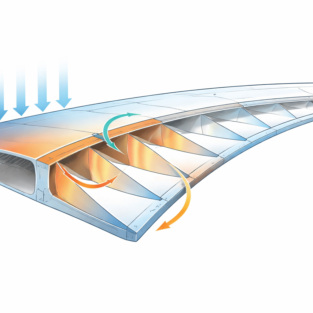
In practice, the outer skins and the inner wingbox are modeled as separate pieces, and their digital meshes do not always line up perfectly. That mismatch can cause trouble in traditional simulations, which usually prefer perfectly matching grids. The authors embrace a hybrid strategy: inside the wingbox, all pieces are neatly matched, but at the interface between skins and wingbox they intentionally allow non-matching panels to keep the modeling simpler and the skins very smooth. They then use a “penalty” coupling technique to gently force displacements and rotations to remain continuous across these imperfect joints. By tuning a single penalty parameter, they can make sure the skin and the inner structure move together realistically under load without making the equations too stiff or unstable.
Testing Bending, Stresses, and Accuracy
To check whether this approach is trustworthy, the researchers use a shell theory that can handle both thin and moderately thick structures and apply it within an isogeometric analysis framework. First they validate their shell formulation and coupling method on a standard square plate problem, confirming that the computed deflections converge to the known solution. They then apply a static bending load to the full RAE wing: the root is clamped, and a gentle upward pressure is applied on the upper skin. They compare the resulting displacements and stresses with those from a finely meshed model built in the commercial finite element code ABAQUS. Despite using roughly fifteen times fewer unknowns than the conventional model, their isogeometric simulations reproduce the same peak deflections and very similar stress patterns, and the stress fields are actually smoother thanks to the underlying high-order surfaces. Systematic refinements in mesh density and curve order show clean convergence toward the reference solution.
Adapting to Many Wing Shapes
Beyond the single benchmark wing, the framework is tested on six additional wings built from widely used airfoils, ranging from symmetric profiles like NACA-0012 to more exotic shapes such as Davis B-24 and AG-16. Each airfoil is first fitted with NURBS curves under strict tolerance control, then extruded into a full wing with skins, ribs, and spars using the same recipe. The bending responses of these wings differ, as expected: some designs prove relatively flexible, others much stiffer and even prone to local buckling near the root. This variety demonstrates that the method can handle very different geometries without special-case modeling, making it suitable for design studies and optimization campaigns in which shapes change repeatedly.
What This Means for Future Aircraft
In simple terms, this work shows how to keep the elegant curves used by aircraft designers all the way through to structural analysis, instead of breaking them into coarse, blocky meshes. By directly using CAD-style surfaces in the computations and carefully gluing together mismatched pieces, the authors achieve accuracy comparable to heavyweight industry tools with far fewer computational resources. This opens the door to faster, more tightly integrated design cycles in which engineers can explore many wing shapes and internal layouts, confident that their virtual tests closely match the true behavior of the structure.
Citation: Wang, D., Cao, X., Xue, Y. et al. Isogeometric analysis of wing structures using multipatch parametrization and penalty-based coupling method. Sci Rep 16, 12393 (2026). https://doi.org/10.1038/s41598-026-42935-9
Keywords: aircraft wing design, structural analysis, isogeometric methods, wingbox modeling, airfoil parametrization