Clear Sky Science · en
Moving standard deviation assisted two-terminal traveling wave based fault location estimation technique for transmission system incorporated with UPFC
Why pinpointing power line troubles matters
When a fault—a short circuit or sudden breakdown—strikes a high‑voltage transmission line, power can flicker, blackouts can spread, and equipment may be damaged. Modern grids now use sophisticated electronics, such as Unified Power Flow Controllers (UPFCs), to push more electricity through existing lines and keep voltages steady. But these devices also make it harder for operators to tell exactly where along a line a fault has occurred. This paper introduces a simpler, faster way to locate such faults with high precision, even when UPFCs and electrical noise complicate the signals.
How power lines behave when things go wrong
Transmission lines stretching hundreds of kilometers act a bit like long metal waveguides. When a fault happens—say a flashover to ground or a contact between phases—it launches sharp electrical “traveling waves” that race along the line in both directions at nearly the speed of light. If engineers can detect the precise instant these waves reach each end of the line, they can calculate where the disturbance started, much like using the arrival times of earthquake waves at different seismometers. This approach, known as traveling‑wave fault location, is very accurate in theory but in practice demands extremely fast measurements and can be thrown off by devices like UPFCs that reshape voltages and currents.
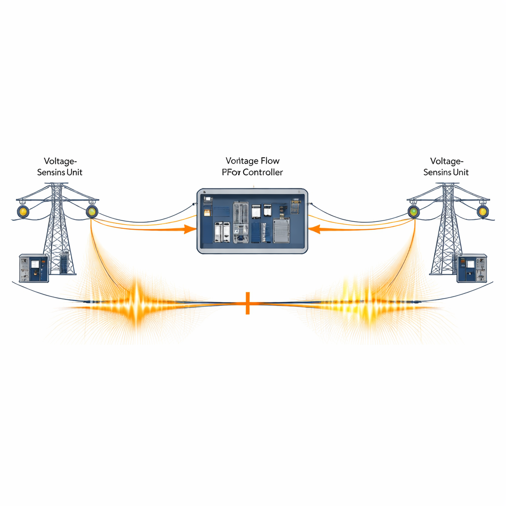
Electronics that help—and hinder—the grid
UPFCs are a powerful class of flexible AC transmission (FACTS) devices that sit in series and in shunt with a transmission line. They can steer power flows, hold voltages within limits, and boost stability, allowing existing corridors to carry more electricity. Yet by injecting and absorbing voltage in controlled ways, UPFCs alter the shape, timing, and strength of the fault‑generated traveling waves that traditional fault‑location schemes expect to see. Existing methods often rely on complex signal transforms, machine‑learning models, or detailed network parameters, and many struggle when sampling rates are modest, noise levels are high, or UPFC settings change. The research gap is a method that remains both simple and robust under these very real operating conditions.
A simpler way to read the waves
The authors propose a fault‑location technique that leans on a basic statistical idea: the moving standard deviation. First, they transform the three‑phase voltages measured at each end of the line into a single “aerial” mode using a standard mathematical rotation (Clarke transformation). This step isolates the part of the signal where fault‑related ripples stand out most clearly. Then, instead of performing heavy signal decompositions, they slide a short time window along this aerial‑mode waveform and compute how much the signal varies inside each window. Whenever a traveling wave arrives, the local variability—and thus the moving standard deviation—rises sharply, creating a distinct peak. By marking the peak times at both terminals and knowing the wave’s propagation speed, the method triangulates the fault location along the line.
Putting the method through real‑world tests
To test the approach, the researchers modeled a 500‑kilovolt, 200‑kilometer transmission corridor equipped with a 100‑megavolt‑ampere UPFC and multiple generators. They simulated a wide variety of fault conditions: different distances along the line, all common fault types (from single‑phase to multi‑phase to ground), a broad range of fault resistances, and many starting angles relative to the power‑frequency cycle. They also stressed the system with close‑in and near‑remote‑end faults, switched the UPFC among its typical operating modes, varied its control targets, reduced the sampling rate down to levels far below what traveling‑wave methods usually need, and added strong noise corresponding to low signal‑to‑noise ratios.
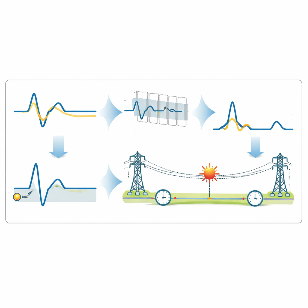
What the results say about grid reliability
Across this daunting set of scenarios, the moving‑standard‑deviation method consistently located faults to within a fraction of a percent of the line length, with typical errors around a few tenths of a kilometer on a 200‑kilometer span. It maintained this precision even when sampling as low as 60 hertz—orders of magnitude below the hundreds of kilohertz often assumed for traveling‑wave schemes—and when signals were heavily contaminated with noise. Compared with more elaborate wavelet, transform, or neural‑network‑based techniques, it achieved similar or better accuracy while running in less than 0.05 seconds and using only terminal voltage measurements. For grid operators, this means a practical tool that can be embedded in existing digital relays or phasor units, offering fast, dependable pinpointing of faults in lines equipped with UPFCs, and ultimately supporting quicker restoration and more resilient power networks.
Citation: Mishra, S., Kumar, R., Kumari, S. et al. Moving standard deviation assisted two-terminal traveling wave based fault location estimation technique for transmission system incorporated with UPFC. Sci Rep 16, 12338 (2026). https://doi.org/10.1038/s41598-026-42393-3
Keywords: power system protection, fault location, traveling waves, FACTS devices, unified power flow controller