Clear Sky Science · en
CFD-DEM coupling analysis of EPB screw conveyor muck discharge in water-rich sandy cobble strata
Digging Safe Tunnels Under Wet, Rocky Ground
As cities expand their subway networks, engineers increasingly have to drive tunnels through treacherous ground: layers of loose sand, fist‑sized cobbles, and high‑pressure groundwater. In these conditions, the giant "earth pressure balance" tunneling machines that normally cut smoothly through the earth can suddenly gush muddy water, stall, or grind themselves down with intense wear. This study explains why those problems occur in the screw conveyor—the machine’s internal "mud elevator"—and shows how a new computer model can predict dangerous blowouts and hidden wear before they threaten a project.
Why This Hidden Machine Part Matters
Inside an earth pressure balance shield, a rotating cutterhead scrapes soil from the tunnel face into a sealed chamber. From there, a long metal screw conveyor meters the excavated mixture of soil, cobbles, and water out of the machine. By carefully controlling how fast that screw turns, operators keep the pressure at the tunnel face just right so the ground above city streets neither sinks nor heaves. In water‑rich sandy‑cobble ground, however, the soil is poorly graded and highly permeable. Large stones can jam the screw while fast‑moving groundwater seeps through gaps, reducing the sealing effect of the muck. The result is a delicate balancing act: transport material efficiently, keep water in check, and avoid grinding the screw to pieces.
A Closer Look Inside the Mud Flow
Previous simulations treated the muck either as a fluid or as a pile of dry particles, which meant they missed the true interaction between rushing groundwater and moving stones. This study combines both views in a single bidirectional model. Water is handled with computational fluid dynamics, which calculates how it flows and how pressure changes along the screw. The cobbles and soil grains are treated as individual particles in a discrete element model that tracks their collisions, friction, and rolling. The two sides constantly exchange information: the water pushes on the particles, while the particles, in turn, block and redirect the water. The model is based on a real project—the Beijing Metro New Airport Line—and was carefully tuned using laboratory tests on wet cobble soils, as well as field data on pressure and torque measured from an operating machine. 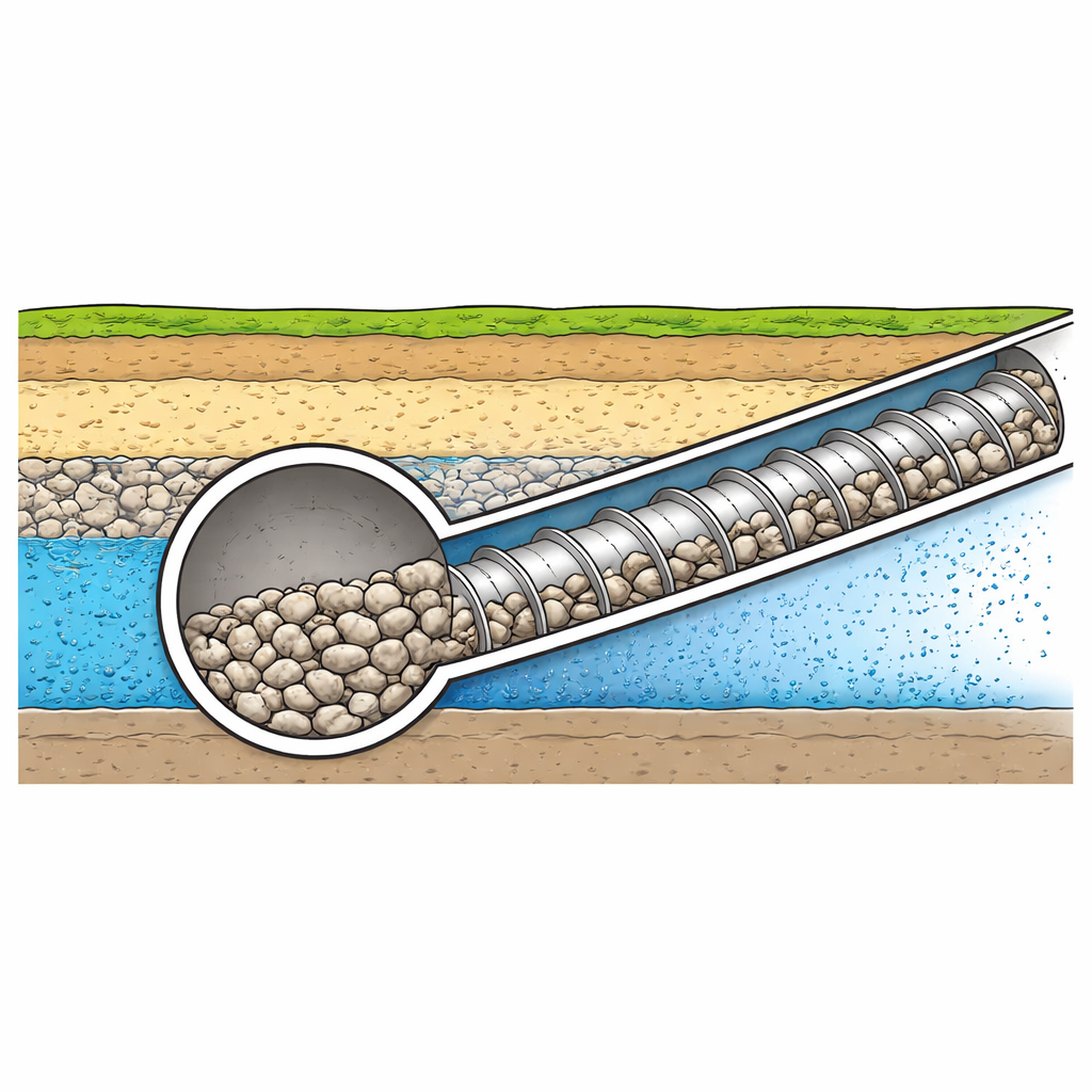
How Water Pressure Tips the System
Using this coupled model, the authors explored what happens as groundwater pressure rises while the earth pressure at the screw inlet is held constant. They introduced a simple indicator, the "water–soil pressure ratio," defined as water pressure divided by earth pressure. When this ratio stayed between about 0.24 and 0.48, pressure along the screw decreased smoothly toward the outlet, and the amount of material coming out matched classic design calculations. The muck behaved like a dense plug that both sealed in pressure and moved steadily. But when the ratio climbed to 0.56—corresponding to a higher water table—the picture changed. Water began to wash fine particles out from between the large cobbles, causing the material to segregate. The screw channel no longer filled properly, and even though the mixture moved faster overall, the volume of solid muck being carried dropped to roughly one‑fifth of the expected value.
Hidden Flow Paths and Uneven Wear
The simulations also revealed how forces and wear concentrate inside the machine. At the bottom of the excavation chamber, a fan‑shaped "preferential flow zone" formed near the screw inlet, where particles streamed toward the conveyor more intensely than elsewhere. Pressure in this zone collapsed to a small fraction of its initial value, creating a pocket of active earth pressure that could draw soil uncontrollably from the tunnel face if the cutterhead openings are too large. Along the screw shaft itself, wear did not peak at a single location but followed a "dual‑peak, three‑stage" pattern: very heavy impact wear right at the inlet, a second, milder but persistent friction peak several meters downstream, and then fading wear toward the outlet. This pattern arises because particles slam into the screw as they first enter, then settle into steady sliding contact in the middle, and finally lose energy near the discharge.
From Computer Insights to Safer Tunnels
For tunnel builders, these findings translate into practical guidance. The water–soil pressure ratio of 0.56 acts as a clear early warning limit: as the ratio approaches this value, operators should watch for signs of reduced filling and particle segregation rather than waiting for a dramatic blowout surge. Designers can reinforce the screw conveyor precisely where the model predicts the two wear peaks, using tougher materials or replaceable liners at the inlet and mid‑length sections, instead of over‑building the entire system. And by adjusting cutterhead opening sizes around the preferential flow zone, they can reduce the risk of uneven loading at the tunnel face. Together, these insights show how a detailed digital view of stones and water moving through a steel screw can help make deep urban tunneling safer, more efficient, and more predictable. 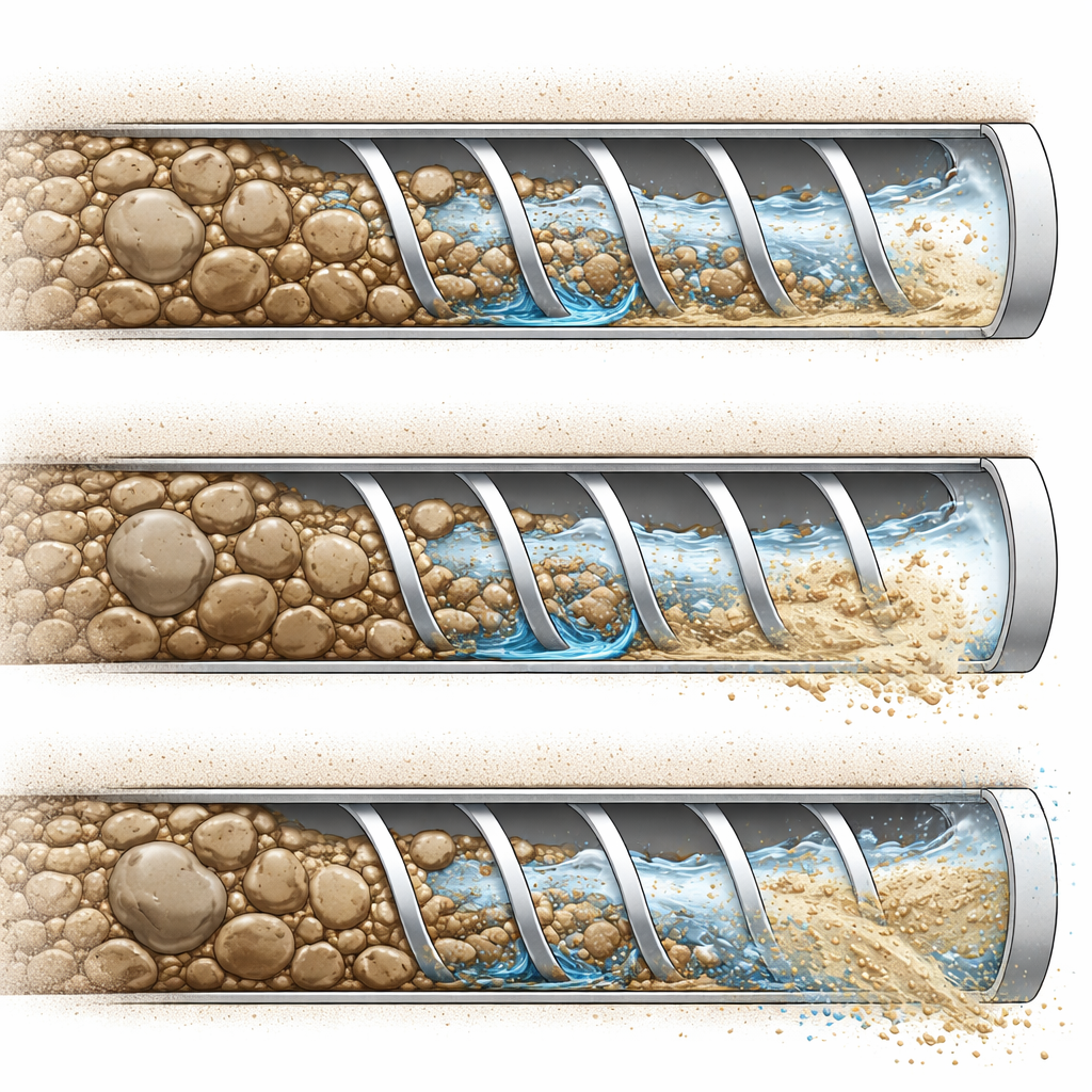
Citation: Guo, C., Liu, G., Wang, X. et al. CFD-DEM coupling analysis of EPB screw conveyor muck discharge in water-rich sandy cobble strata. Sci Rep 16, 12407 (2026). https://doi.org/10.1038/s41598-026-41903-7
Keywords: shield tunneling, screw conveyor, water-rich sandy cobble, CFD-DEM simulation, tunnel blowout