Clear Sky Science · en
A high-selectivity 24-GHz SIW–DGS–CPW bandpass filter with wide stopband rejection for automotive radar and ADAS
Sharper Eyes for Safer Cars
Modern cars rely on radar to notice what drivers might miss: a child stepping into the street, a sudden stop in traffic, or a motorcycle in a blind spot. For that radar to work well, it must listen to just the right slice of the radio spectrum and ignore the rest. This paper presents a tiny, finely tuned “radio gatekeeper” designed specifically for 24‑gigahertz automotive radar and advanced driver‑assistance systems (ADAS). By combining several clever microwave structures into a single compact part, the authors build a filter that passes the wanted radar signals cleanly while strongly rejecting unwanted clutter and interference, even under the harsh temperatures found under the hood of a car. 
Why Clean Radar Signals Matter
Radar in cars works by sending out high‑frequency radio waves, then measuring the faint echoes that bounce off vehicles, pedestrians, and obstacles. If nearby electronics or neighboring communication bands leak into the radar’s listening window, those echoes can be muddied, shortening detection range or producing false alarms. A bandpass filter is the component that carves out a narrow, well‑defined window in frequency so that the radar “hears” mostly its own echoes. At 24 GHz—a popular band for short‑ and medium‑range automotive radar—this part must be both very selective and very small, to fit into crowded modules without adding much loss or heat. Existing designs often trade compact size against sharp frequency control or lack careful testing over real‑world temperatures.
A Compact Gatekeeper on a Single Layer
The researchers tackle this challenge by integrating three microwave building blocks on one flat circuit board. First, they use substrate integrated waveguide (SIW) cavities—rectangular zones bordered by rows of metal holes—that trap and guide the desired radar frequency with high quality. Second, they etch special shapes in the ground metal under the circuit, known as defected ground structures (DGS). These act like precisely placed notches that create deep “dead zones” for unwanted frequencies near the operating band, sharpening the filter’s edges. Third, they feed the structure with a coplanar waveguide (CPW), a type of surface transmission line that eases connection to other chip and board components. The interplay of these three features produces a narrow passage for the target band while blocking a wide range of neighboring signals, all within an 18 × 36 mm footprint—small enough for dense radar front ends.
From Design Tweaks to Real Hardware
To refine performance, the team runs extensive simulations that show how changing geometry affects behavior. Adjusting the spacing between key slots alters how strongly the two SIW cavities interact, which in turn tunes bandwidth and how steeply the filter’s response falls off. Varying the board’s thickness reveals an optimal value where electric and magnetic energy are balanced for a clean, stable passband at 24 GHz. The authors also build a simple “lumped” circuit model with inductors and capacitors that mimics the full 3D structure; its predictions match detailed electromagnetic simulations, giving designers an intuitive handle on how each feature—the cavities, the DGS cuts, and the CPW feed—contributes to the final response. 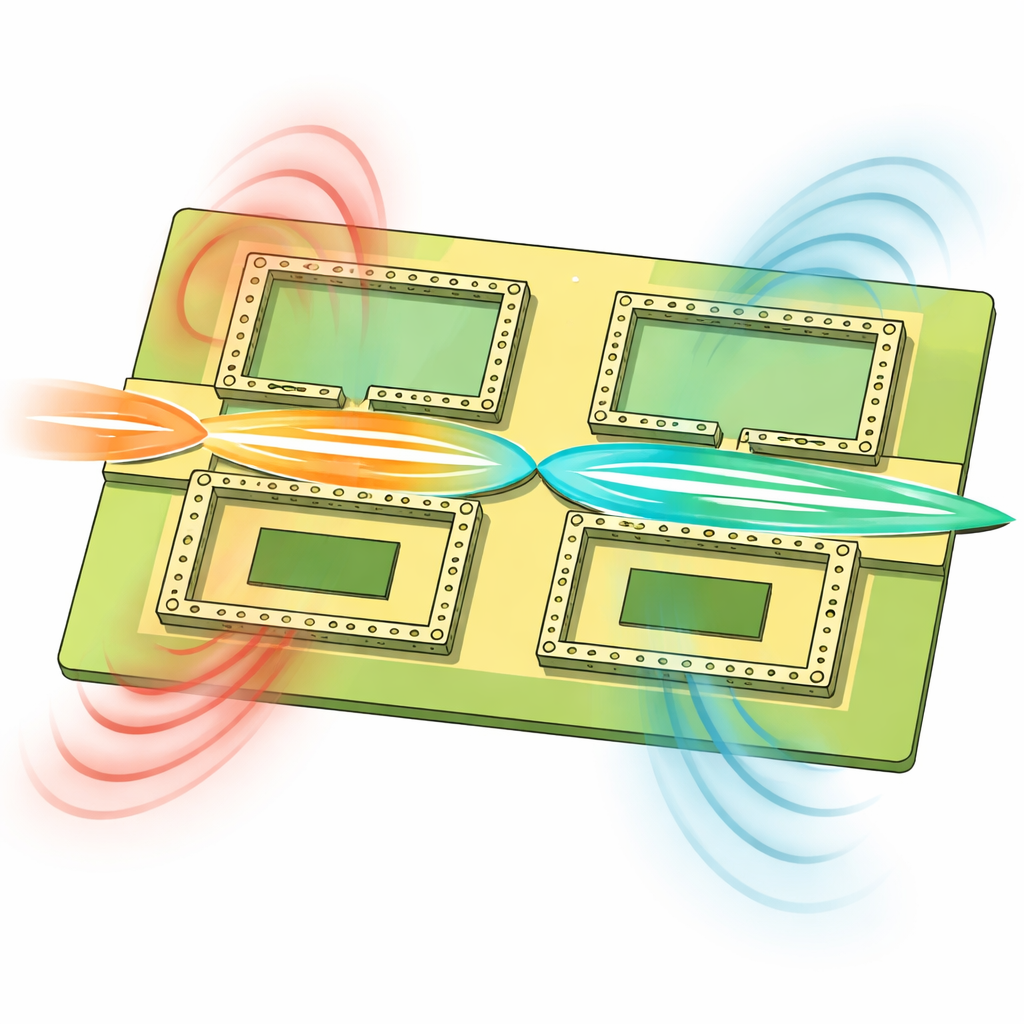
Holding Steady in the Heat
Because car electronics must survive sweltering engine bays and cold mornings, the filter’s stability with temperature is crucial. The team exposes the design, both in simulation and in measurement, to temperatures from 25 °C to 105 °C. As the metal and substrate expand slightly, the filter’s center frequency drifts downward by only about 30 MHz—roughly one‑eighth of its 450 MHz useful bandwidth—while signal loss and reflection remain nearly unchanged. In the lab, a fabricated prototype measured with a high‑frequency network analyzer confirms the predictions: the filter centers around 24 GHz, shows in‑band loss of about 1.6–2.0 dB, and suppresses unwanted signals by 30–40 dB over a wide range of nearby frequencies.
What This Means for Future Driver Aids
To a non‑specialist, the takeaway is that the authors have engineered a small, efficient, and robust “frequency gate” tailored for 24‑GHz automotive radar. By carefully shaping how radio energy flows through a single‑layer circuit, they obtain sharper distinction between wanted radar echoes and unwanted noise than many comparable designs, without sacrificing size or resilience to heat. Such filters can help radar sensors see more clearly and consistently, which in turn supports safer automatic braking, lane keeping, and collision‑avoidance features in next‑generation vehicles.
Citation: Abada, A.M., El-Hameed, A.S.A., Eldamak, A.R. et al. A high-selectivity 24-GHz SIW–DGS–CPW bandpass filter with wide stopband rejection for automotive radar and ADAS. Sci Rep 16, 9810 (2026). https://doi.org/10.1038/s41598-026-41312-w
Keywords: automotive radar, ADAS, 24 GHz bandpass filter, substrate integrated waveguide, defected ground structure