Clear Sky Science · en
The effects of normal fault movement on the failure mechanism of water conveyance tunnels considering multi-field interaction
Why underground water tunnels can fail during earthquakes
Many cities and farming regions depend on long underground tunnels to move water from mountains to where people live. These lifeline tunnels often cut across active faults—cracks in the Earth that can suddenly shift during earthquakes. When a fault under a tunnel moves, the ground on each side is pushed in different directions, stretching and bending the structure. This study looks at how such fault movement damages large water tunnels and what design choices can make them safer.
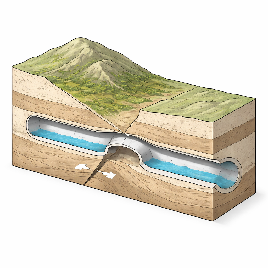
What happens when a fault cuts through a water tunnel
The researchers focus on a common type of fault called a normal fault, where one side of the rock drops downward relative to the other. In many past earthquakes, the worst tunnel damage has been found right where the tunnel crosses the fault, even when the surrounding rock appears solid. Cracks, broken concrete, and even collapses have been recorded at these crossings. For drinking-water and irrigation systems, such failures can interrupt supply, cause leaks and erosion, and be very difficult and costly to repair deep underground.
A virtual experiment that includes rock, concrete, and flowing water
To explore this problem, the authors built a detailed three-dimensional computer model of a large, pressurised water tunnel passing through a normal fault. The model includes the surrounding rock, a weaker fractured fault zone, the reinforced concrete shell of the tunnel, and the water flowing inside. Two specialised software tools are linked: one calculates how the solid rock and concrete deform and crack, while the other simulates the turbulent water flow. A coupling platform lets these two worlds “talk” to each other, passing back and forth how the tunnel moves and how the water pushes on it. Before running large numbers of simulations, the team checked their model against a scaled laboratory “sandbox” test of a tunnel crossing a fault. The numerical tunnel bent and cracked in almost the same way as the physical model, especially in terms of where deformation concentrated and where the largest cracks formed, giving confidence that the virtual setup captures the key behaviour.
Where and how the tunnel gets hurt
Across all simulated scenarios, one pattern was clear: fault movement produced very localised damage. The concrete lining in the fault zone and a limited stretch—tens of metres—on either side suffered severe distortion, while the rest of the long tunnel remained almost elastic, with little permanent change. The most vulnerable spots were the crown (top) and invert (bottom) of the tunnel near the fault, where bending and shearing combine to pull the concrete apart in tension. The authors used a single damage index, called the Overall Lining Damage in Tension (OLDT), to roll up how badly the lining is cracked over a tunnel section. As fault slip increased, this index climbed rapidly in the fault zone, approaching a state that corresponds to near-complete loss of function, while staying low elsewhere.
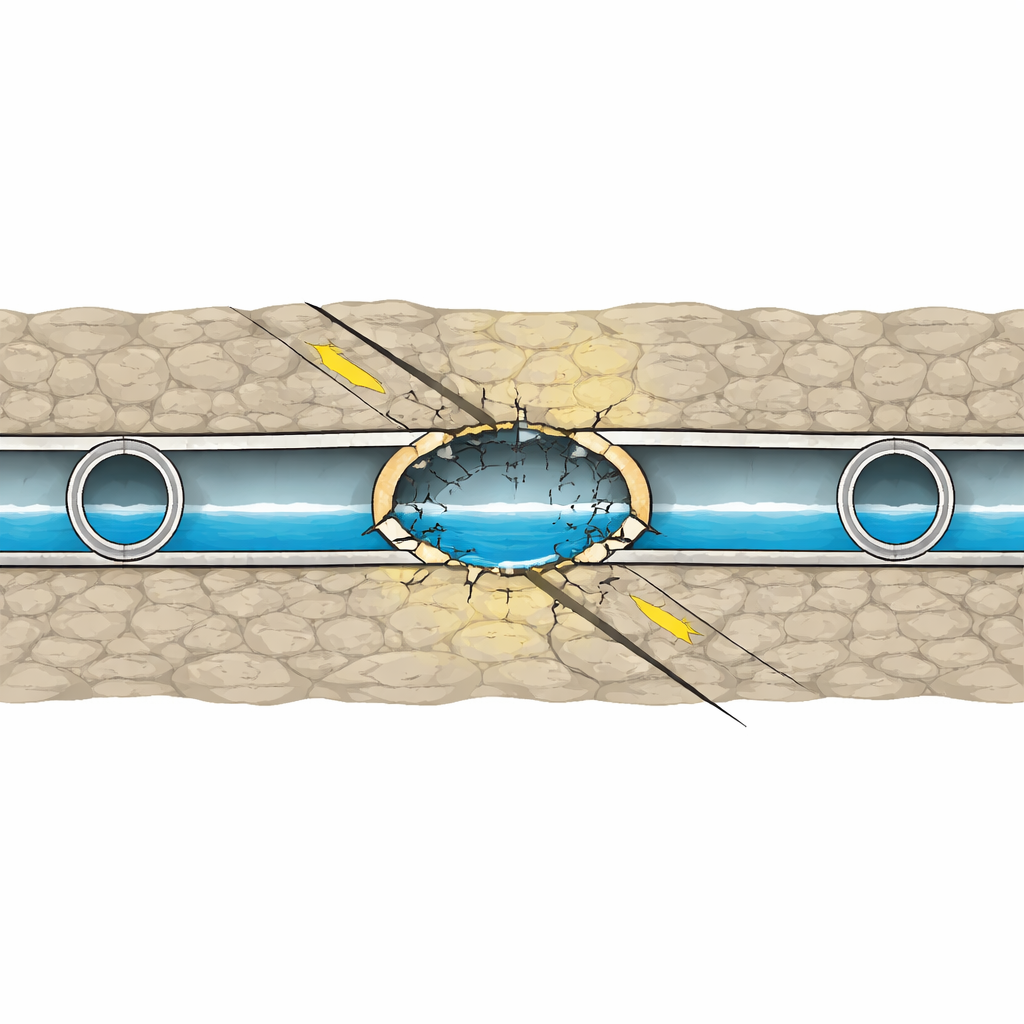
How geology and design choices change the outcome
The team then varied five main factors: how much the fault slips, the angle of the fault, how wide the fractured zone is, how strong that weak zone is, and how strong the tunnel lining concrete is. Larger fault displacements strongly raised the damage index in the fault zone, confirming that permanent ground offset is a main driver of failure. Steeper fault angles and wider fractured zones mainly changed how far along the tunnel the deformations spread, but did not drastically raise peak damage. In contrast, making the fault zone “tougher” (more cohesive) or using higher-strength concrete linings both shrank the severely damaged region and lowered the damage index. Interestingly, the pressurised water inside the tunnel slightly shifted the stress patterns in the lining but did not fundamentally change the way the tunnel failed; the primary control remained the relative stiffness of rock, fault zone, and lining.
What this means for safer water lifelines
For engineers, the message is that design effort should concentrate on the cross-fault section of a water tunnel rather than the entire alignment. Reinforcing or grouting a very weak fault zone, and using stronger lining materials or special detailing where the tunnel intersects the fault, can greatly reduce the risk of through-cracking and collapse, even if a large fault slip occurs. The study also shows that a single quantitative damage index, such as OLDT, can help compare design options and set performance targets. In essence, while normal fault movement is a serious hazard, careful design of both the rock treatment and the tunnel lining around the fault can keep these critical water conveyance tunnels functioning when they are needed most.
Citation: Xinwei, Z., Zhanxiang, C. & Weiheng, L. The effects of normal fault movement on the failure mechanism of water conveyance tunnels considering multi-field interaction. Sci Rep 16, 12447 (2026). https://doi.org/10.1038/s41598-026-41070-9
Keywords: water conveyance tunnels, normal faults, seismic tunnel damage, fluid–structure interaction, underground infrastructure safety