Clear Sky Science · en
Fiber-optic Fabry–Pérot interferometric accelerometer with composite cavity and temperature calibration for high-temperature and high-pressure applications
Watching the Heartbeat of a Nuclear Plant
Inside a nuclear power plant, thousands of metal tubes quietly shuttle scalding water and steam that drive the turbines. If any of these tubes vibrate too strongly, they can wear out, crack, or even rupture, risking costly shutdowns and safety concerns. This paper describes a new kind of light-based motion sensor that can sit directly on these tubes, shrug off intense heat and pressure, and listen for tiny tremors long before damage occurs. 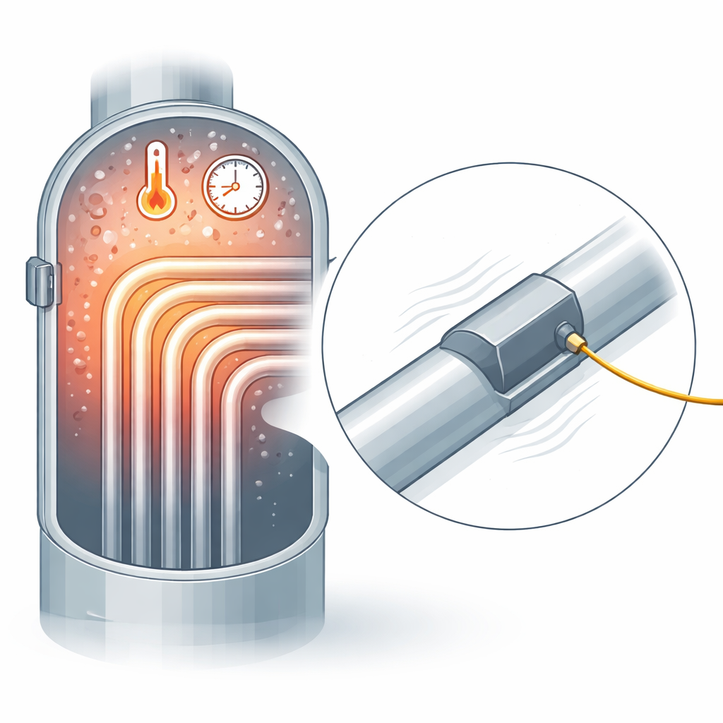
Why Tube Vibrations Matter
Modern nuclear reactors rely on steam generators packed with slender heat-transfer tubes. Flowing coolant can make these tubes vibrate, slowly rubbing against supports and neighboring tubes. Over years of operation, this “flow-induced vibration” can thin the walls or open cracks, threatening the barrier that keeps radioactive water separated from the rest of the plant. Engineers would like to measure these vibrations continuously and precisely, but common electronic accelerometers struggle in the harsh mix of high temperature, high pressure, strong radiation, and electromagnetic noise found inside the reactor system.
Measuring Motion with Light Instead of Wires
The authors turn to fiber optics—hair-thin glass strands that carry light—to build an accelerometer that is immune to electrical interference and comfortable at high temperatures. Their device is based on a Fabry–Pérot cavity, a tiny gap where light bounces back and forth between reflective surfaces. The color pattern of the reflected light shifts when the gap changes length by mere billionths of a meter. In this sensor, a small central mass is supported by a set of carefully shaped beams etched from silicon. When the tube accelerates, the mass moves slightly, changing the length of an air-filled cavity and thus the optical signal sent back through the fiber.
Separating Heat from Motion
One major challenge in such environments is that heat itself can mimic motion: materials expand, fibers creep, and the optical cavity length drifts, confusing real vibration with thermal changes. To tackle this, the team creates a “composite cavity” built from two layers of glass with a silicon diaphragm between them. One cavity, in glass, responds mainly to temperature; the other, in air near the moving mass, responds to acceleration. Crucially, the end of the optical fiber is no longer a mirror inside the cavity, so thermal expansion of the fiber does not directly disturb the measurement. By analyzing the returning spectrum with fast mathematical tools, the system extracts both cavity lengths separately and uses a calibration database to convert them into accurate temperature and acceleration readings in real time. 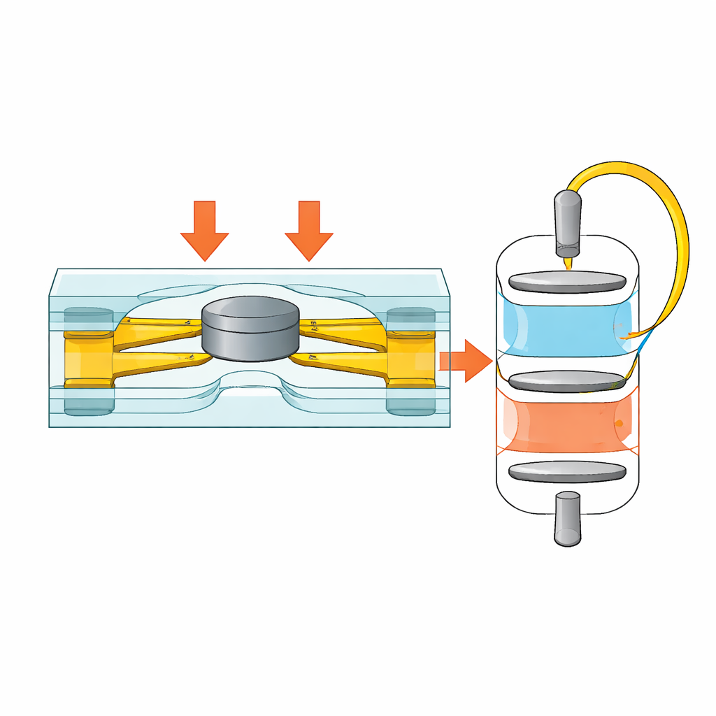
Built for Harsh Conditions
The sensor chip is made using microfabrication techniques similar to those used for computer chips, allowing precise control over the shape and thickness of the beams that support the mass. Simulations guide the design to balance sensitivity—how much the mass moves for a given acceleration—against the resonant frequency, which sets the usable bandwidth. A symmetric layout of multiple beams ensures that sideways shocks do not significantly tilt or twist the mass, keeping “cross-axis” errors very low. The finished chip is sealed between glass layers, mounted in a compact metal package, and paired with a 45-degree mirror and tiny lens that fold the light path so the device fits in the cramped space around reactor tubing while protecting the fiber from tight bends.
How Well It Performs
Laboratory tests show that at room temperature, the sensor can detect accelerations with a sensitivity of about 4.53 nanometers of cavity change per unit of g (the pull of gravity), and a usable range up to roughly ±238 g without distortion. Its main resonance appears around 7.45 kilohertz, comfortably above the tens-of-hertz vibration range typical of steam generator tubes, so it can track their motion cleanly. The cross-axis contribution—false signals from sideways motion—is less than half a percent. Most importantly, when placed at 350 °C and 17.5 megapascals of pressure, conditions similar to those inside a pressurized water reactor, the device ran for 60 hours with cavity drift under a tenth of a nanometer. Sensitivity actually increases somewhat with temperature, but the built-in temperature cavity and calibration model allow those effects to be corrected.
What This Means for Nuclear Safety
In straightforward terms, the authors have built a tiny, rugged “stethoscope” that listens to the vibration of vital metal tubes deep inside a nuclear plant without being fooled by heat or sideways jolts. By combining a dual-cavity optical design, symmetric mechanical structure, and robust high-temperature packaging, their accelerometer can deliver long-term, precise motion readings where conventional sensors fail. This makes continuous health monitoring of steam generator tubes more practical, helping operators catch early signs of wear and protect both plant performance and safety over decades of operation.
Citation: Qin, F., Tan, J., Guo, J. et al. Fiber-optic Fabry–Pérot interferometric accelerometer with composite cavity and temperature calibration for high-temperature and high-pressure applications. Microsyst Nanoeng 12, 155 (2026). https://doi.org/10.1038/s41378-026-01250-z
Keywords: fiber-optic accelerometer, nuclear power monitoring, high-temperature sensors, Fabry–Pérot cavity, flow-induced vibration