Clear Sky Science · en
Aliasing in near-field array ambiguity functions: a spatial frequency-domain framework
Why giant antenna arrays matter
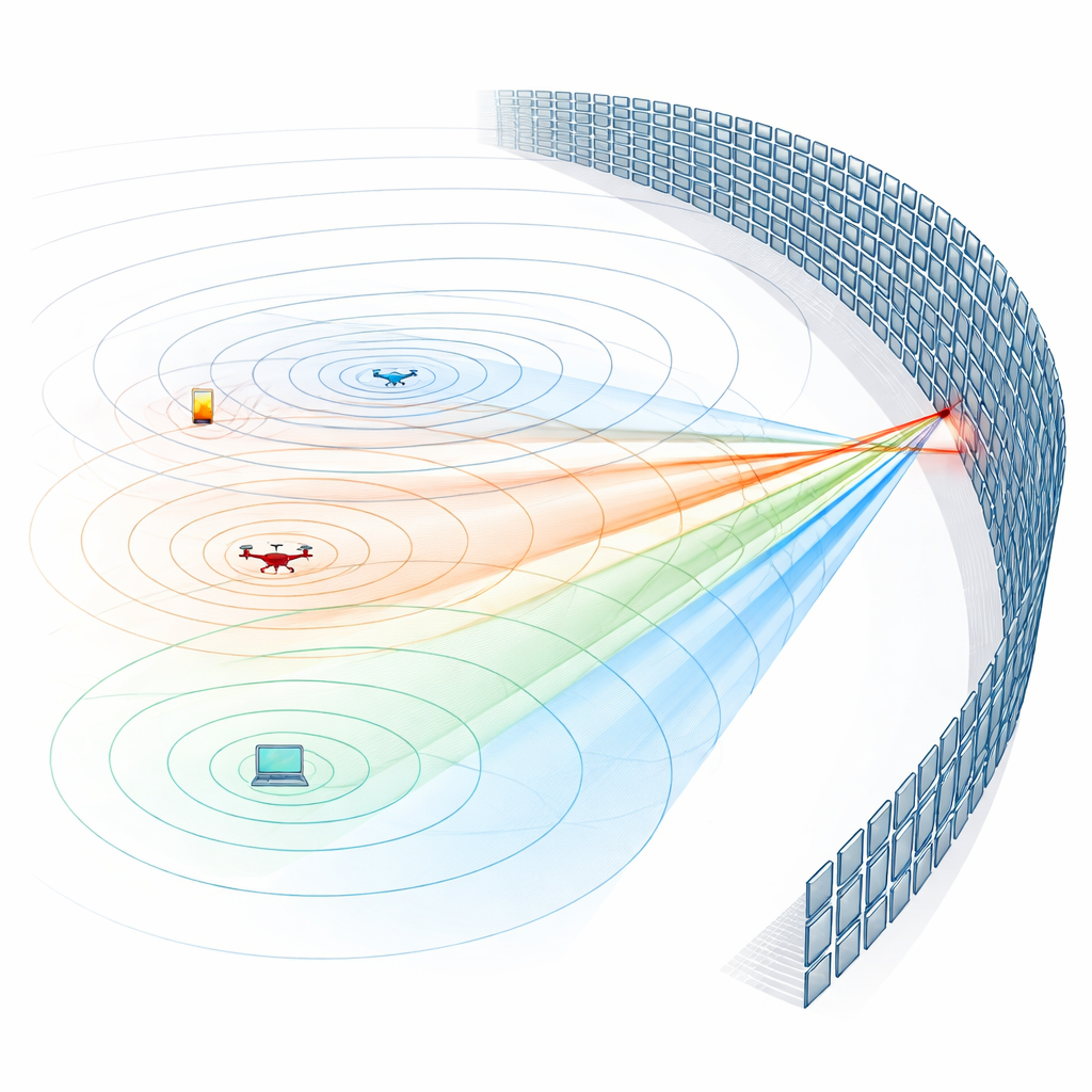
As we move toward future 6G wireless networks, engineers are planning antenna systems so large that they begin to sense the three-dimensional shape of radio waves instead of treating them as flat sheets. These “extremely large-scale arrays” promise centimeter-level positioning, sharper beams, and more efficient use of the airwaves. But they also introduce new kinds of ghost signals and confusion points that can mislead a receiver about where a device really is. This paper explains where those ghosts come from and how to predict and avoid them.
From simple beams to complex patterns
Traditional antenna arrays are designed for the far field, where radio waves can be approximated as flat planes. There, a simple spacing rule—keeping antennas about half a wavelength apart—prevents spurious strong responses called grating lobes, which look like extra beams pointing in the wrong directions. With extremely large arrays, devices sit much closer, in the near field, where the wavefront is curved like expanding ripples. In this regime, a single array can sense both the distance and direction of a device, enabling high-precision localization and beam focusing. At the same time, the resulting patterns of response in space become much more intricate, and the familiar far-field rules no longer describe where the dangerous ghost responses will appear.
Ghost beams as a kind of spatial aliasing
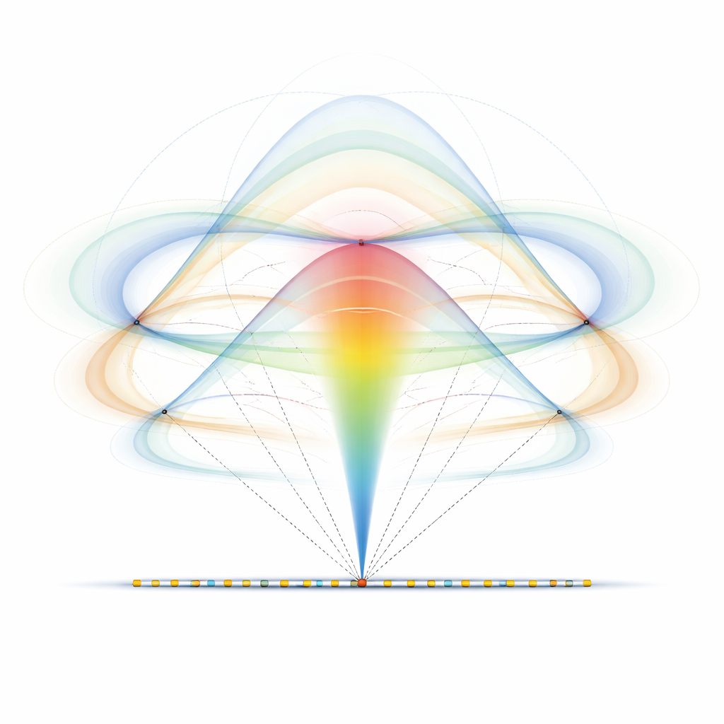
The authors study these effects through a central tool called the ambiguity function, which measures how easily a system can confuse one location with another. In an ideal world, the ambiguity function would spike only when the tested position exactly matches the true device position. Real, finite arrays instead produce a bright main lobe surrounded by weaker side lobes. Some of these side lobes stem from the physics of focusing; others are artifacts created when a continuous wavefield is sampled only at the discrete antenna locations. The team shows that, in the near field, the most robust way to define grating lobes is as "spatial aliasing artifacts": they arise when the spatial frequencies present in the wave pattern exceed what the discrete array sampling can represent without folding and overlap, much like audio sampled too coarsely produces spurious tones.
Tracking spatial frequencies locally
To make this aliasing behavior tractable, the paper introduces a local spatial-frequency viewpoint. As a wave from a device sweeps along the array, its phase does not advance at a constant rate; it speeds up and slows down like a chirp signal. The authors describe this by a local wave number that varies from point to point on the array. They show that the most relevant spatial frequencies for aliasing can be captured by this local quantity, giving a "soft" band limit that tracks where most of the energy in the ambiguity function’s spectrum resides. If all these local frequencies stay below a threshold set by the antenna spacing, the discrete ambiguity function matches its continuous counterpart closely, and no strong aliasing-induced ghosts appear.
Designing safe operating zones
Building on this picture, the authors define two practical concepts. First, an aliasing-free region around a given true device position: the set of nearby test positions that can be probed without inducing aliasing in the ambiguity function. Its boundary forms eye- or ring-shaped curves in space and depends on the antenna geometry and spacing. Second, an aliasing-safe operating domain: a region in which any pair of positions can be distinguished without aliasing, for a given array design. They derive general design guidelines—densifying an array (adding antennas without enlarging it) always helps, extending the physical size tends to shrink the aliasing-free region, and the classical half-wavelength spacing rule guarantees aliasing-free behavior even in the near field if a continuous path of such spacings connects all antennas.
What the framework reveals for common arrays
The paper then applies the framework to two widely used array shapes. For long uniform linear arrays, the authors obtain closed-form formulas describing the aliasing-free region as a characteristic “eye” around each device location. They show how this eye scales with antenna spacing, array length, and device distance, and how it smoothly reduces to the familiar far-field picture where only angles, not ranges, matter. For uniform circular arrays, treated as a ring of antennas surrounding an area, the same analysis yields circular or eye-shaped aliasing fronts whose radius depends on wavelength, angular spacing, and how large a portion of the circle is actually populated with antennas. These results translate complex numerical patterns into geometric shapes that can guide array layout.
Takeaway for future wireless systems
In essence, the article turns a messy, near-field problem into a clean geometric one: by watching how local spatial frequencies evolve along an array, designers can map where aliasing-induced grating lobes will appear, without needing unwieldy exact formulas. This makes it possible to define safe operating regions and spacing rules for gigantic arrays used in 6G-era communication and localization. While the present work focuses on where such ghost responses can exist rather than how strong they are, it lays the theoretical groundwork needed to refine array designs, extend the analysis to more intricate geometries and wideband signals, and ultimately build near-field systems that deliver high resolution without being fooled by their own ghost images.
Citation: Monnoyer, G., Louveaux, J., Defraigne, L. et al. Aliasing in near-field array ambiguity functions: a spatial frequency-domain framework. npj Wirel. Technol. 2, 21 (2026). https://doi.org/10.1038/s44459-026-00043-0
Keywords: near-field arrays, spatial aliasing, 6G localization, grating lobes, antenna design