Clear Sky Science · en
Load-bearing and failure behavior of welded horizontal joints in prefabricated shear wall structures
Why safer prefab buildings matter
More and more buildings are being made from large factory-built concrete panels that are quickly assembled on site. This approach can cut construction time, reduce waste, and improve quality control. But in earthquake-prone regions, one big question remains: how well do the metal joints that connect these heavy concrete pieces actually hold up when the ground shakes? This study takes a close look at a key type of welded connection between walls and floors in prefabricated buildings to see how strong and damage-tolerant it really is.
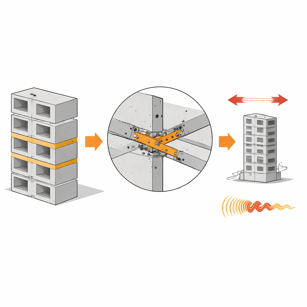
How modern buildings are pieced together
In a traditional concrete building, walls and floors are poured as a near-continuous mass, so the structure behaves like a single block. Prefabricated buildings are different: walls and slabs are made in a factory, then joined together on site. Those joints become the “weak links” that control safety and repair costs during an earthquake. Engineers can use "wet" joints, which add cast-in-place concrete on site, or "dry" joints, which rely on bolts or welds. Wet joints behave more like solid concrete but slow down construction. Dry joints are faster and cleaner, yet their behavior during strong shaking is not as well understood, especially for welded joints that run horizontally where walls meet floors.
A new welded link between walls and floors
The authors designed a practical welded joint system aimed at real-world construction. Steel plates are cast into the edges of the wall panels and floor slab in the factory. On site, a connecting plate is welded between these embedded plates, with steel bars tying the plates into concealed beams and columns inside the concrete. This creates a hidden steel “bridge” that transfers forces between the wall above, the floor, and the wall below. Two full-scale specimens were built: one representing an outer wall connected to a floor on one side, and another representing an inner wall linked to floors on both sides. Both were mounted in a test frame and pushed back and forth to imitate the slow, repeated drifts caused by strong earthquakes.
What happened when the shaking was simulated
During testing, the joints carried lateral forces of about 330 kilonewtons—comparable to the weight of several small trucks—before their strength began to drop. They also allowed top displacements of around 40–44 millimeters while still holding most of their load, indicating good ductility, or ability to deform without suddenly snapping. Cracks first appeared in the lower wall near the welded plates, then spread diagonally, and eventually concrete at the compressed edge of the wall crushed while the steel plates and bars near the joint yielded. The failure pattern was a blend of sideways shearing at the joint and bending of the wall—rather than a brittle, sudden break. The specimen representing inner walls, which had floors on both sides, showed slightly higher stiffness and strength than the outer-wall version, reflecting a more balanced force path.
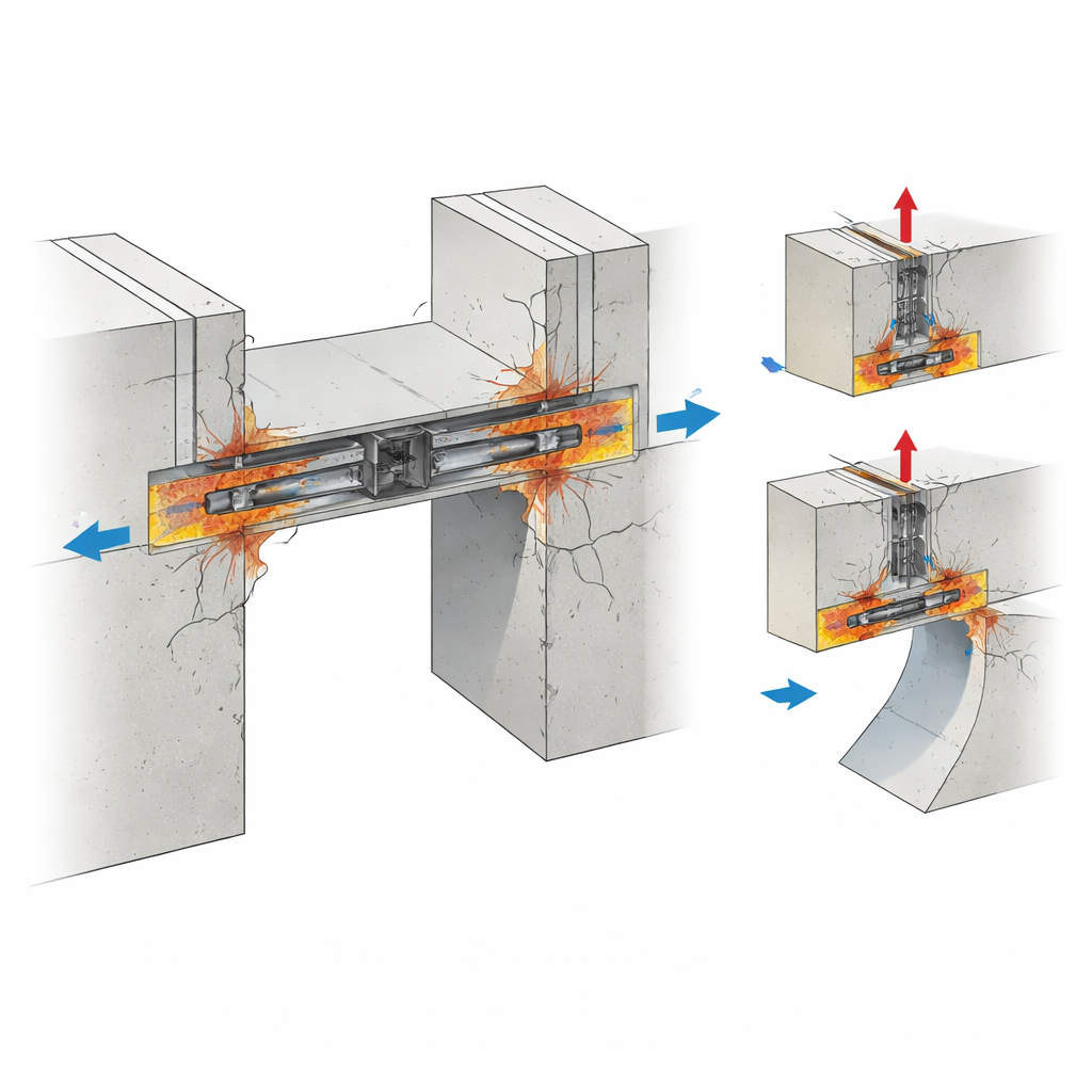
Peering inside with virtual testing
To complement the lab experiments, the team built a detailed three-dimensional computer model using the ABAQUS simulation program. They used an advanced concrete model that can capture cracking, crushing, and stiffness loss under repeated loading, combined with simplified but realistic steel behavior. After calibrating the model, they found that the simulated force–displacement curves, stress hotspots, and crack patterns matched the tests reasonably well: peak and yield loads were typically within 10–20 percent of the measured values. With this validated tool, they ran virtual experiments to see how changing the vertical load on the wall (axial compression) and the wall’s geometry (shear-span ratio) affected performance. Higher compression increased peak strength but reduced deformation capacity beyond a certain point, while taller, more slender walls shifted behavior from shear-dominated damage toward bending-dominated damage and lower strength.
What this means for earthquake-resistant design
For non-specialists, the key message is that carefully detailed welded joints between prefabricated walls and floors can perform robustly under earthquake-like loading. These joints did not act as fragile seams; instead, they carried large forces, dissipated energy through controlled cracking and steel yielding, and failed in a gradual, observable way. The study also shows that designers must balance vertical load and wall proportions to avoid overly stiff, compression-crushing failures and to preserve ductility. Finally, the validated computer model provides a powerful tool for refining joint details and exploring more extreme scenarios, helping engineers design prefabricated buildings that are both quick to build and safer when the ground shakes.
Citation: Xu, B., Xu, Y. & Zhang, Y. Load-bearing and failure behavior of welded horizontal joints in prefabricated shear wall structures. Sci Rep 16, 10262 (2026). https://doi.org/10.1038/s41598-026-40936-2
Keywords: prefabricated concrete, seismic joints, welded connections, shear walls, earthquake engineering