Clear Sky Science · en
Nonlinear magnetic ring model based on impedance measurements with DC-bias current
Why this matters for everyday electronics
From phone chargers to electric cars, modern power electronics quietly rely on magnetic components to steer and smooth electrical energy. These parts often operate under harsh, rapidly changing currents, where their behavior becomes strongly nonlinear and difficult to predict. This paper introduces a practical way to turn detailed measurements of a magnetic ring into a ready‑to‑use circuit model that engineers can plug directly into standard simulation tools. The goal is simple but powerful: make simulations of real magnetic components behave much closer to what actually happens in hardware, even when the currents are pushed close to their limits.
From lab measurements to a digital twin
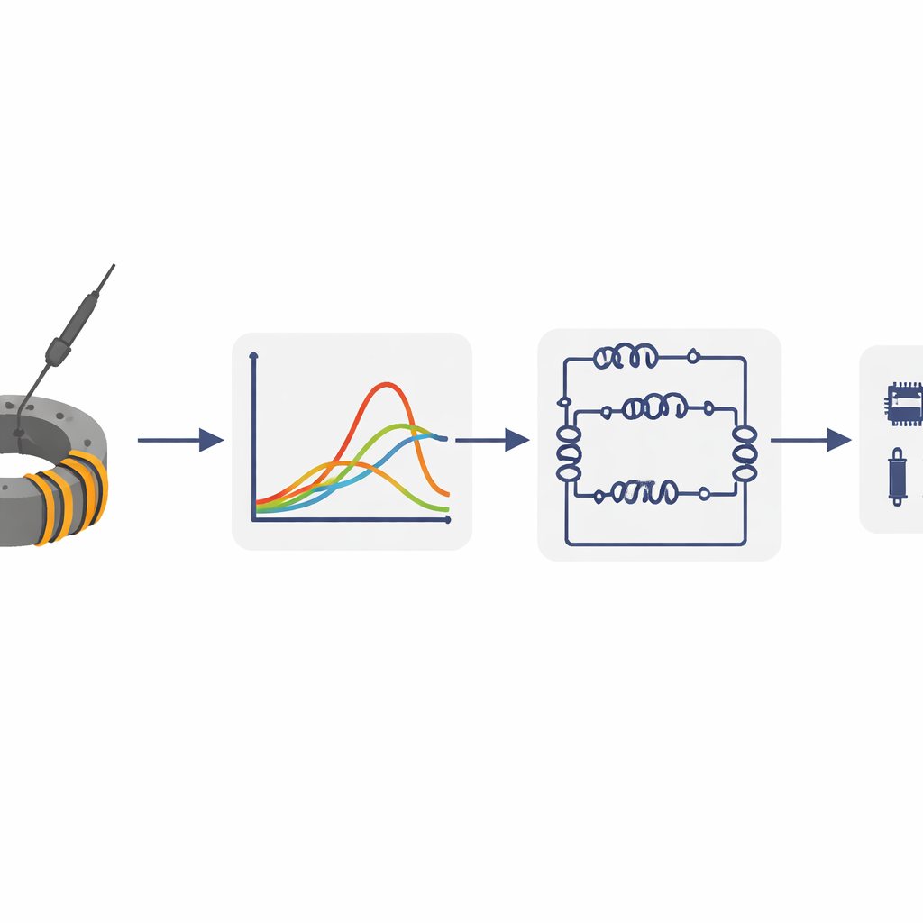
The authors start with a common magnetic part: a ring‑shaped core made from a nanocrystalline alloy, carrying up to 800 A of direct current and probed across frequencies from 100 Hz to 10 MHz. Instead of only observing how the magnetic field responds, they focus on how the ring’s electrical impedance — its combined resistance and inductance — changes with both frequency and current. By sweeping a small alternating current on top of a large steady current, they build a two‑dimensional map of the ring’s behavior, capturing crucial effects such as energy loss (hysteresis), frequency‑dependent response, and magnetic saturation, where the material can no longer easily store more magnetic energy.
Turning complex behavior into a simple circuit
To make this rich measurement data useful in design, the team represents the ring as a chain of simple building blocks: pairs of an inductor and a resistor connected in parallel. Each pair behaves like a small “slice” of the overall magnetic response, and together they reproduce the measured impedance over frequency and current. Unlike fixed components, the effective inductance and resistance of each slice depend on the current flowing through the ring. The authors extract these current‑dependent curves using two fitting strategies: a classical nonlinear least‑squares method and a more flexible approach based on an unsupervised neural network. Both produce smooth, physically reasonable parameter functions, but the neural network allows more freedom in how each slice changes with current.
Embedding the ring model in standard simulations
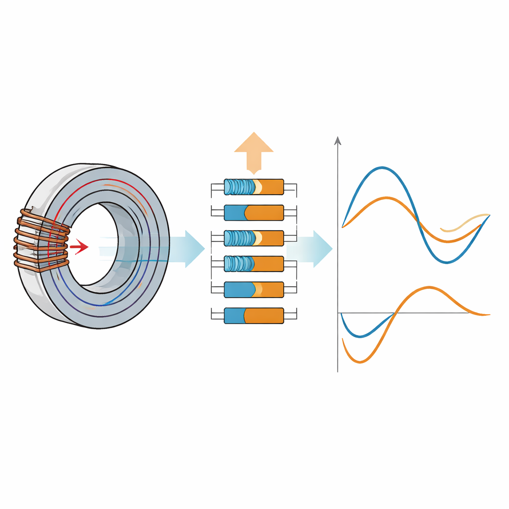
Having defined the circuit structure, the next challenge is to implement it in SPICE, the workhorse software for circuit simulation. Directly inserting many nonlinear inductors and resistors can make simulations unstable or extremely slow. To avoid this, the authors design a specialized SPICE subcircuit for a single lossy inductive block that uses behavioral sources and a unit inductance to compute voltage from an integral of the fitted inductance curve. This construction ensures that the overall impedance smoothly follows the measured current‑dependent behavior, while remaining numerically stable even when the impedance changes by orders of magnitude over very short times. Chains of these subcircuits then form a digital twin of the magnetic ring that can be dropped into larger power‑electronics models.
Putting the model to the test
The researchers do not stop at curve fitting: they test the model in three increasingly demanding ways. First, they feed small sinusoidal currents with various steady biases into the SPICE circuit and check that the simulated impedance matches the analytic expression used in the fitting; the errors are below 1%, showing that the implementation faithfully reproduces the intended model. Second, they drive the model with large, rapidly varying currents that swing the ring from full negative to full positive saturation. When an analytical solution is available for a simplified case, the simulated voltage across the ring closely tracks it, confirming numerical stability even in the strongly nonlinear regime. Third, they compare simulations against a dedicated high‑current experiment, where a capacitor bank and spark gap generate damped oscillatory currents up to 800 A, and both voltage and current are recorded on a real ring.
Strengths, limits, and what it means in practice
In the high‑current experiment, the simulated and measured voltages agree well in overall shape and timing, and the model reproduces the expected loss of magnetic response after saturation. The largest differences appear in the peaks at very high currents and around the transition from linear to saturated behavior. The authors trace these discrepancies to several sources: non‑ideal measurement data, limits of the fitting algorithms, and physical effects at extreme operating conditions that are not fully captured by the simplified series of inductive–resistive blocks. Nonetheless, for small signals riding on a strong direct current — the typical case in many filters and converters — the model is highly accurate and robust.
Take‑home message
For a non‑specialist, the key outcome is that this work turns a difficult, physics‑heavy problem — how a real magnetic ring behaves over a huge range of frequencies and currents — into a compact circuit model that runs reliably in mainstream simulation tools. Engineers can now design and test power‑electronics systems using a virtual component that closely mirrors a specific magnetic ring measured in the lab, including its nonlinearities and losses. While the method is not yet perfect for the most extreme high‑current swings, it already offers a powerful, practical step toward more trustworthy simulations and better‑designed magnetic components in everyday electronic hardware.
Citation: Kutorasiński, K., Pawłowski, J., Molas, M. et al. Nonlinear magnetic ring model based on impedance measurements with DC-bias current. Sci Rep 16, 11846 (2026). https://doi.org/10.1038/s41598-026-39594-1
Keywords: magnetic core modeling, power electronics, nonlinear magnetics, SPICE simulation, impedance measurement