Clear Sky Science · en
Design methods for imaging with freeform optics
Why Bend Light in New Ways?
Modern cameras, telescopes, and head‑mounted displays are under pressure to be smaller, lighter, and sharper than ever before. Traditional lenses and mirrors are usually smooth and symmetrical, like perfect bowls or domes, which makes them easier to design and build—but also limits what they can do. This paper explains how a new class of “freeform” optical surfaces, which can be shaped almost arbitrarily, is changing the rules of imaging. It reviews how engineers now describe these unusual shapes, how they design systems that use them, and how they make sure such systems can actually be manufactured in the real world.
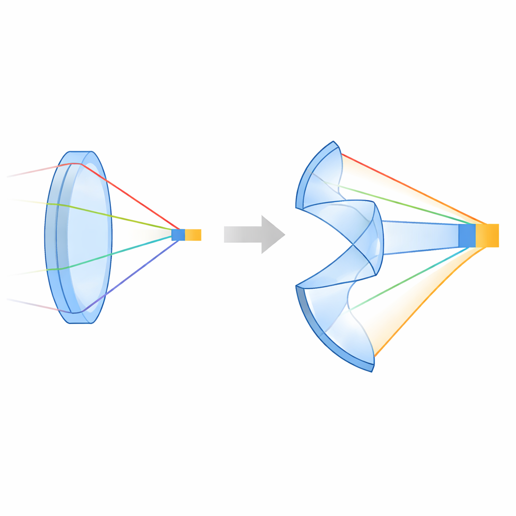
From Simple Curves to Freeform Surfaces
Classical optics relies heavily on rotational symmetry: if you spin a lens around its central axis, it looks the same from all directions. That symmetry simplifies both the math and the hardware, and it works well for systems with circular fields of view, like standard cameras. However, many useful systems—such as telescopes without central obstructions, wide‑angle head‑worn displays, or compact instruments tucked into tight spaces—break that symmetry. Once symmetry is broken, new kinds of image errors, called aberrations, appear that cannot be tamed with ordinary shapes alone. Freeform surfaces, defined broadly as optical surfaces with no axis of rotational invariance, offer far more freedom to control these errors, enabling wider fields of view, higher numerical apertures (brighter images), and more compact layouts.
Mathematical Tools for Shaping Light
To exploit freeform optics, designers first need a precise language for describing surface shape. The paper surveys many such mathematical descriptions. One common strategy starts with a simple “base” shape, like a sphere, conic, toroid, or biconic, and then adds extra terms that describe how the actual surface departs from this base. These departures are often written using sets of polynomials that behave nicely in calculations—for example, they are orthogonal, meaning each term controls a distinct pattern on the surface. Well‑known sets include Zernike polynomials for circular apertures and various extensions for rectangular or other shapes. The choice of description affects optimization speed, how easily people can understand and share designs, and how directly surface parameters connect to manufacturability (for instance, how steep the slopes are and how difficult the surface will be to test.
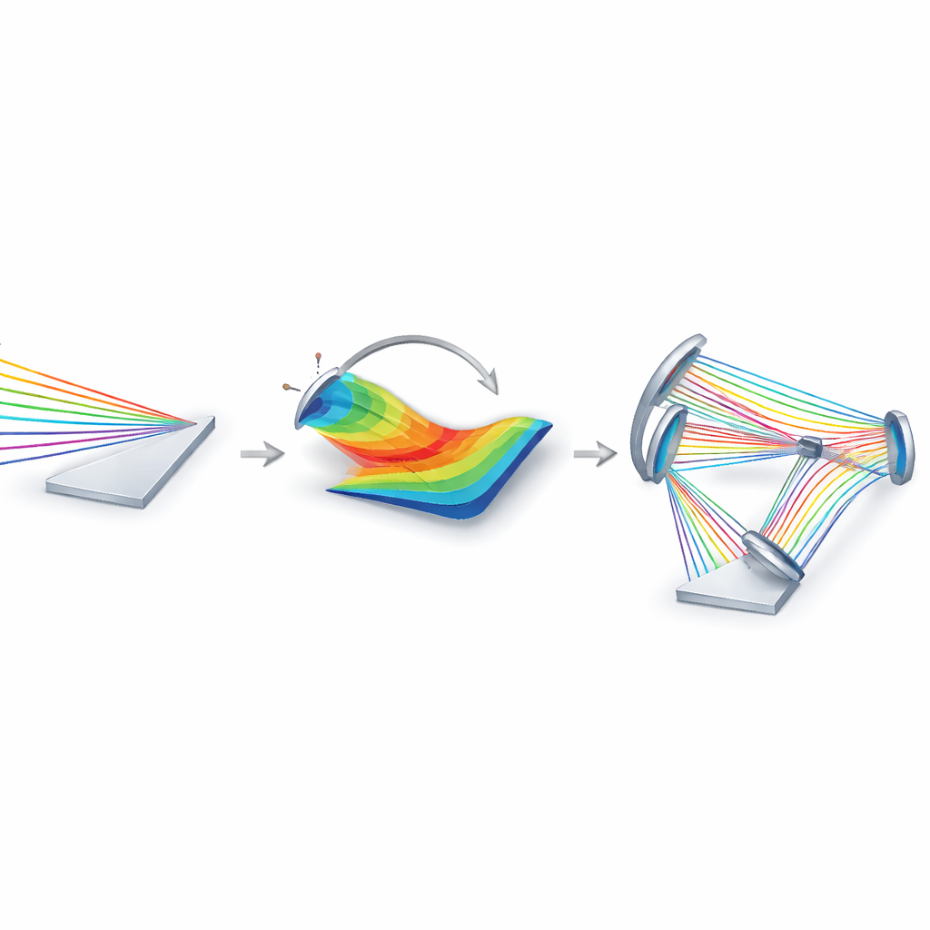
Designing Systems: Theory, Construction, and Automation
Once surfaces can be described, the next challenge is deciding what shapes they should take inside a complete imaging system. The paper groups design strategies into several broad families. Aberration‑based methods use advanced theory to predict how each surface contributes to blurring across the field and then deliberately place and shape freeform elements to cancel the most troublesome errors. Direct design methods construct surfaces more geometrically, either by solving differential equations derived from ray‑tracing laws or by building the shape point‑by‑point so that all light paths from object to image have the same optical length. A third family hands much of the work to computers: machine‑learning approaches and automatic physics‑based solvers generate starting designs or even near‑final systems from high‑level specifications such as field of view, focal length, and package constraints.
Making Exotic Optics Practical
High performance on a computer screen is only half the story; freeform systems must also be buildable and alignable at reasonable cost. The review therefore devotes a full section to design‑for‑manufacture strategies. Some exploit fabrication tricks, such as diamond‑turning multiple mirrors on a single block so their alignment is “baked in,” or machining several freeform surfaces on a shared cylindrical substrate. Others introduce manufacturability metrics—like total departure from a simple base or sensitivity to small tilts and shifts—and penalize them during optimization, yielding designs that are more tolerant of real‑world errors. The authors emphasize that manufacturability depends on the entire production chain, from polishing and molding to metrology, and they advocate closer collaboration between designers, fabricators, and testers.
Where Freeform Optics Is Headed Next
The paper closes by comparing the strengths and weaknesses of the main design approaches and outlining emerging directions. These include better head‑to‑head benchmarks for surface descriptions and algorithms, extending methods to fully three‑dimensional layouts with no symmetry at all, and deeper integration of artificial intelligence while keeping physical insight in the loop. The authors also highlight hybrid components that blend freeform shapes with metasurfaces or gradient‑index materials, as well as dynamically adjustable freeform elements for adaptive imaging. For a non‑specialist, the key message is that by freeing optical surfaces from traditional symmetry and pairing them with smart design methods and manufacturing‑aware thinking, engineers can build imaging systems that are both more capable and more compact than ever before.
Citation: Aaron Bauer, Nick Takaki, and Jannick P. Rolland, "Design methods for imaging with freeform optics," Optica 12, 1775-1793 (2025). https://doi.org/10.1364/OPTICA.575611
Keywords: freeform optics, imaging systems, optical design, aberration correction, manufacturability