Clear Sky Science · en
On the relevance of facesheet orifice geometry to acoustic liner impedance
Why tiny holes matter for quieter planes
Most modern passenger jets already fly with special "sound-absorbing" panels lining their engine inlets to keep cabin and community noise down. At first glance these panels look simple: a sheet of metal with lots of tiny holes sitting over a honeycomb cavity. This study shows that even barely visible differences in how the edges of those holes are finished—rounded, beveled, or perfectly sharp—can change how well the liner absorbs sound by tens of percent. That means details usually treated as minor manufacturing imperfections can quietly undermine, or unexpectedly boost, noise reduction.
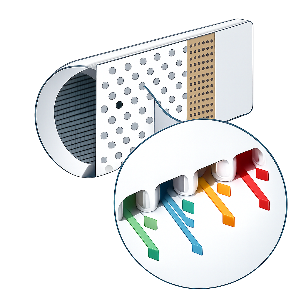
Inside the walls that eat sound
Acoustic liners act a bit like thousands of miniature bottle-shaped resonators embedded in the engine wall. Incoming sound waves push air in and out of the small holes in the front sheet, and energy is lost to friction and heat as the air rubs against the walls and swirls inside the cavities. Engineers normally design these systems assuming neat, ideal holes. In practice, however, the holes are only about a millimeter across, and the way they are drilled or 3D-printed leaves subtle edge shapes: slightly rounded lips, small bevels (chamfers), or nearly razor-sharp rims. Earlier measurements on real hardware had already hinted that such tiny details could shift the acoustic performance by up to about 30%, but it was unclear why.
Virtual experiments with perfect control
To isolate the role of hole-edge shape, the authors turned to high-fidelity computer simulations using a lattice-Boltzmann fluid solver. They modeled a standard laboratory setup called a normal impedance tube, where controlled sound waves travel straight down a duct and strike a test sample. The sample was an aircraft-style liner with a perforated facesheet over a honeycomb cavity. Starting from a 3D scan of a real liner (with slightly rounded edges), they created three idealized variations: a perfectly sharp-edged hole, a hole with chamfers on both sides, and a hole with only the top edge chamfered. They then drove the system with strong tones—130 and 145 decibels, at 800, 1400, and 2000 hertz—and computed how much of the sound was reflected, transmitted, or absorbed.
Small edge changes, big sound differences
The simulations showed a clear and consistent trend. When the hole edges were sharp, the liner offered the highest resistance to the motion of air through the holes and delivered the strongest sound absorption across all tested frequencies and sound levels. Rounding or chamfering the edges reduced this resistance by up to about 28% and lowered the absorption accordingly. A symmetric double chamfer behaved very similarly to the scanned, rounded geometry, both giving the lowest resistance and highest air flow rate through the holes. The asymmetric case—chamfered only on the incident side—fell in between: it partially eased the flow in one direction but still created extra losses when the air reversed. These patterns mirror the variations seen in earlier tube measurements taken at different locations on the same liner panel, where the hole finish varied from place to place.
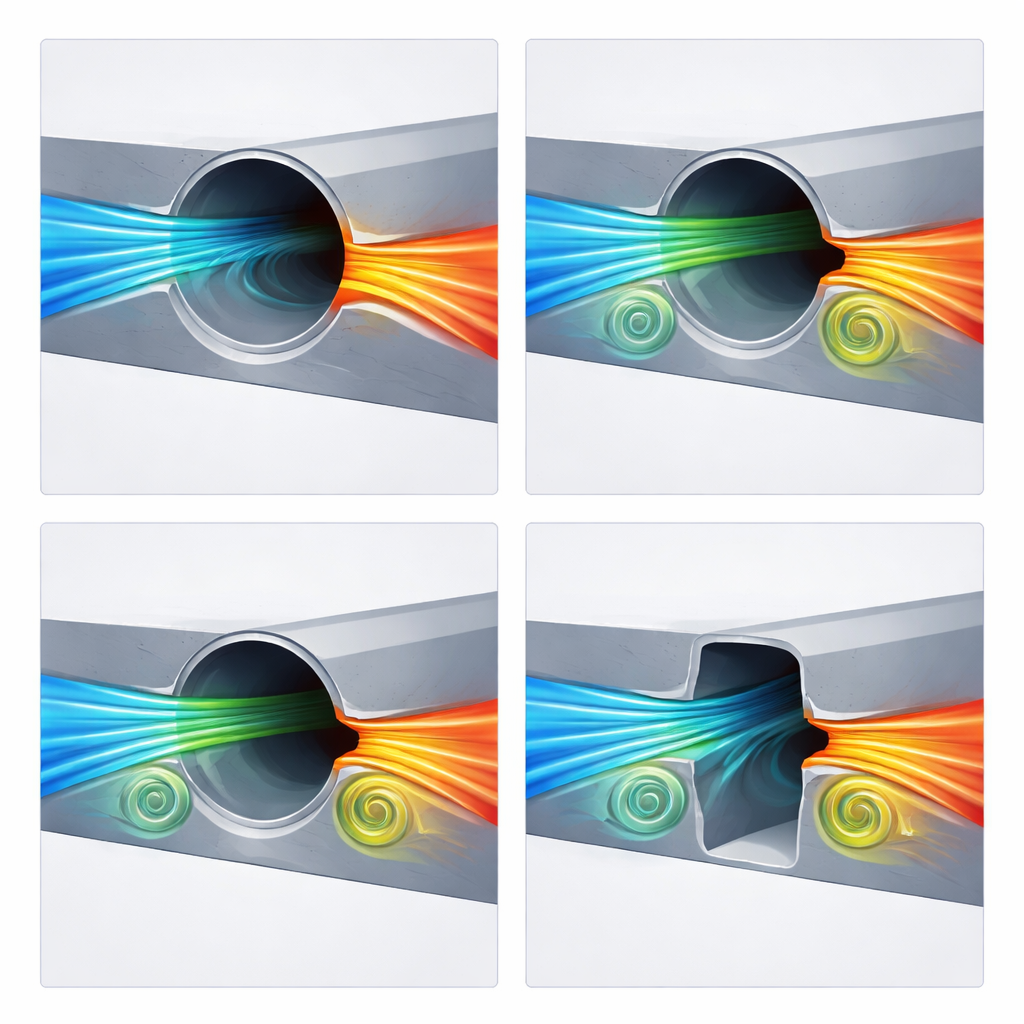
What the air is actually doing
To understand why edges matter so much, the team looked inside the holes at the detailed motion of the air. Sharp rims produced a strong "vena contracta" effect: as air was driven in and out, it squeezed into a narrow jet and peeled away from the wall, creating pronounced recirculating regions and strong velocity fluctuations. These features reduced the effective flow area and limited the net mass of air moving through each oscillation, while at the same time increasing the friction and mixing that sap acoustic energy. Rounded and double-chamfered edges allowed the air to follow gentler paths with less separation and weaker vortices, so more air flowed but less sound energy was dissipated. The single-top-chamfer design mixed both behaviors, with smoother inflow but still a sharp-edged, jet-like outflow. Overall, the study revealed that even in conditions considered "linear" by engineering standards, the fine-scale fluid dynamics at the orifice rim dominate the acoustic behavior.
Implications for quieter, reliable designs
For non-specialists, the takeaway is that "small" geometric imperfections in aircraft noise liners are not minor at all. When holes are only a millimeter or so wide, changing the edge by a fraction of that size shifts how the air moves and how much sound is absorbed. This work shows that real-world variations introduced by machining or 3D printing can easily alter liner performance by amounts that matter for meeting strict airport noise limits. The authors argue that designers and manufacturers should treat edge shape as a controlled design parameter, not an afterthought—using tighter tolerances, better inspection (such as 3D scanning), and simulation tools that include these details, to ensure that the liners installed on aircraft actually deliver the noise reduction promised on paper.
Citation: Avallone, F., Khedr, A., Paduano, A. et al. On the relevance of facesheet orifice geometry to acoustic liner impedance. npj Acoust. 2, 6 (2026). https://doi.org/10.1038/s44384-026-00044-x
Keywords: aircraft noise, acoustic liners, perforated facesheet, orifice geometry, turbofan engines