Clear Sky Science · en
Experimental evaluation and accuracy analysis of inductive current transformers under realistic nonlinear and harmonic-rich load conditions
Why power meters can quietly drift off
Behind every electricity bill, protective relay, or smart meter sits a humble device called a current transformer. Its job is to shrink large currents down to safe, measurable levels. This paper asks a timely question: as homes and factories fill with electronics that warp the current waveform, can these long‑trusted transformers still be relied on to tell the truth? By recreating real‑world, distortion‑heavy conditions in the lab, the authors show in detail when and how current transformers start to mislead us.
From neat waves to messy reality
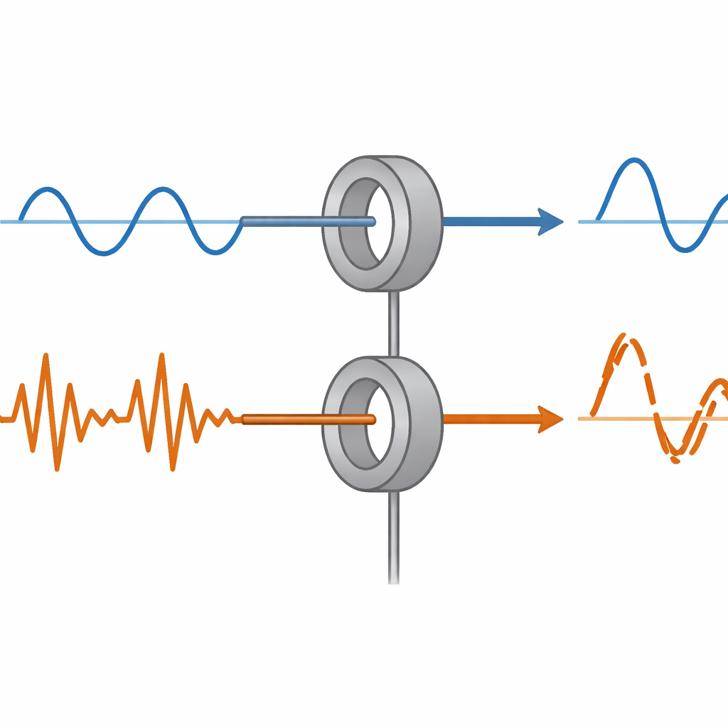
In a textbook, electric current is drawn as a smooth sine wave. In real buildings, however, devices such as motor drives, televisions, discharge lamps, and power supplies gulp current in short, uneven bursts. These “nonlinear” loads fill the current with extra frequency components, called harmonics, and push transformer cores away from their comfortable operating region. The study focuses on two widely used low‑voltage current transformers, rated 50/5 A and 100/5 A, and asks how faithfully they can reproduce both tame, nearly sinusoidal currents and these far messier waveforms.
A realistic test bench in the lab
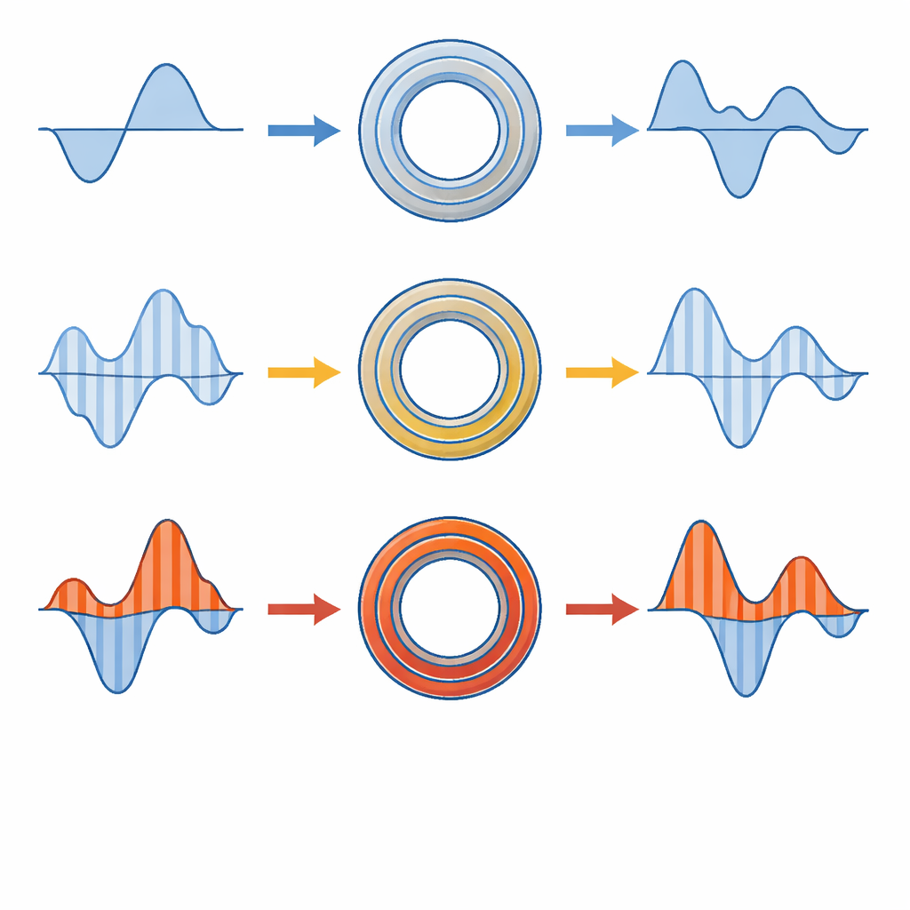
To probe this question, the researchers built a laboratory setup that mirrors industrial practice. A 230 V AC source feeds real appliances arranged to create seven different load conditions, from simple linear operation to strongly pulsed, asymmetric currents. A precision resistor in the main line records the “true” current, while the two current transformers, wired in series, provide their scaled‑down versions. A digital oscilloscope captures synchronized waveforms and computes several key indicators: the root‑mean‑square (RMS) current, which underpins energy billing; total harmonic distortion (THD), which tracks how far a waveform departs from a pure sine; the ratio error between actual and measured current; and the phase error, or timing shift between primary and secondary currents.
What happens as distortion and current climb
Under gentle, nearly sinusoidal conditions, both transformers behave as their datasheets promise. They reproduce the current with only tiny ratio errors below 1% and very small phase shifts, and their harmonic distortion is only slightly worse than the source. As soon as nonlinear loads enter the picture, the story changes. Pulsed, highly distorted currents drive the magnetic cores toward saturation. The transformers then underrate or overrate the true current, show large ratio errors that can exceed 40%, and add substantial extra distortion. At the same time, the phase of the secondary current slips behind or ahead of the primary by several degrees, which can be critical for protective relays that must react in milliseconds.
High current alone can be a problem
The experiments also reveal that even when the waveform looks almost ideal, simply pushing the current to high levels can break the usual assumptions. In one test with a clean but high‑magnitude current, the 50/5 transformer severely underestimated the true RMS current, with ratio errors above 60% and THD soaring beyond 100%, clear fingerprints of deep core saturation. The higher‑rated 100/5 transformer fared better but still showed sizable errors. Across all seven cases, the same pattern emerged: as either current level or harmonic content increased, amplitude and phase errors grew together, showing that conventional accuracy classes defined only for sinusoidal testing do not describe what really happens in today’s distorted grids.
What this means for grids and future fixes
For a lay reader, the takeaway is straightforward: when the current waveform is strongly distorted, ordinary current transformers can make currents look smaller or different than they really are, and their timing can drift. That combination undermines accurate billing, misguides grid planning, and can delay or mis‑trigger protection systems. By carefully mapping how errors grow with distortion and load, this study supplies the “ground truth” needed to improve standards and to design smarter correction methods. It points toward future solutions such as real‑time error monitoring, harmonic compensation, and artificial‑intelligence models that predict when a transformer is slipping out of its safe operating zone. Together, such advances could keep measurement devices honest, even as our power networks become ever more crowded with nonlinear electronics.
Citation: Daouli, B.H.L., Mana, H., Labiod, C. et al. Experimental evaluation and accuracy analysis of inductive current transformers under realistic nonlinear and harmonic-rich load conditions. Sci Rep 16, 8933 (2026). https://doi.org/10.1038/s41598-026-41709-7
Keywords: current transformers, harmonic distortion, nonlinear loads, measurement accuracy, power quality