Clear Sky Science · en
Design and cutting performance analysis of cylindrical gear skiving tool with uniform working rake angle
Sharper Gears for Everyday Machines
From car transmissions to wind turbines, many of the machines we rely on every day depend on gears that must mesh smoothly for years under heavy loads. Making these gears fast, accurately, and at low cost is surprisingly difficult. This study introduces a new way to design the specialized cutting tool used in a process called gear skiving, aiming to produce more precise gears, extend tool life, and reduce machining problems such as heat, vibration, and wear.
Why Gear Cutting Needed a Rethink
Modern industries favor gear skiving because it can cut complex internal and external gears quickly and accurately. However, the traditional skiving tools, which have a conical shape and a flat front cutting surface, come with serious drawbacks. As these tools are resharpened over time, their geometry subtly changes, causing gear accuracy to drift. The flat cutting face also leads to sections of the cutting edge that bite into metal at unfavorable angles, making chip removal harder, increasing cutting forces, and causing localized heating. Together, these effects shorten tool life, raise costs, and make it harder to keep gears within tight tolerances.
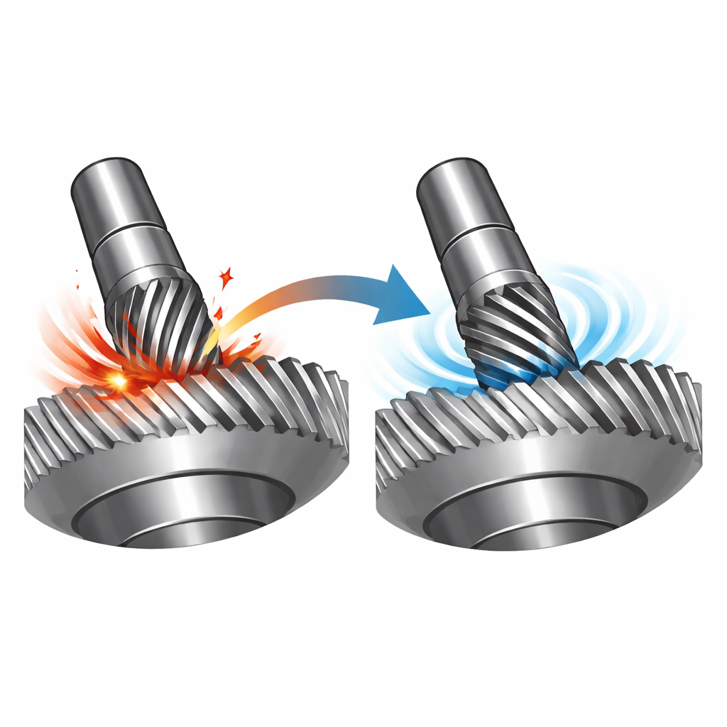
A New Shape for a Smoother Cut
The authors propose a different geometry: a cylindrical gear skiving tool whose front cutting surface is gently curved instead of flat, and whose side surface wraps around in a controlled helix. They design this tool so that the “working rake angle”—the effective angle at which the edge meets the metal—is kept uniform along the entire cutting edge, even when the tool is used in an offset position relative to the gear. By carefully modeling the motion of the tool and gear together, they ensure that the edge remains a precise mirror, or conjugate, of the gear tooth it is cutting. The side surface of the tool is shaped as a helical cylinder so that clearance between tool and gear is maintained without using a fragile built-in relief angle that would be lost during regrinding.
Putting the Design to the Test in the Computer
To see how this new tool behaves before building it, the team constructed detailed computer simulations using the finite element method. These simulations coupled mechanics and heat flow, allowing the researchers to watch cutting forces, chip formation, and temperature fields evolve as the tool skived a gear tooth. They systematically varied three key process settings: how fast the tool spins, how quickly the gear is fed through the cut, and how deep each pass cuts into the material. The analysis showed that feed rate has the strongest influence on cutting forces, while rotation speed governs how hot the cutting zone becomes. Across many settings, the curved-face tool produced more stable forces and a more even temperature field than the traditional flat-face design, even if the peak force in one direction was slightly higher.
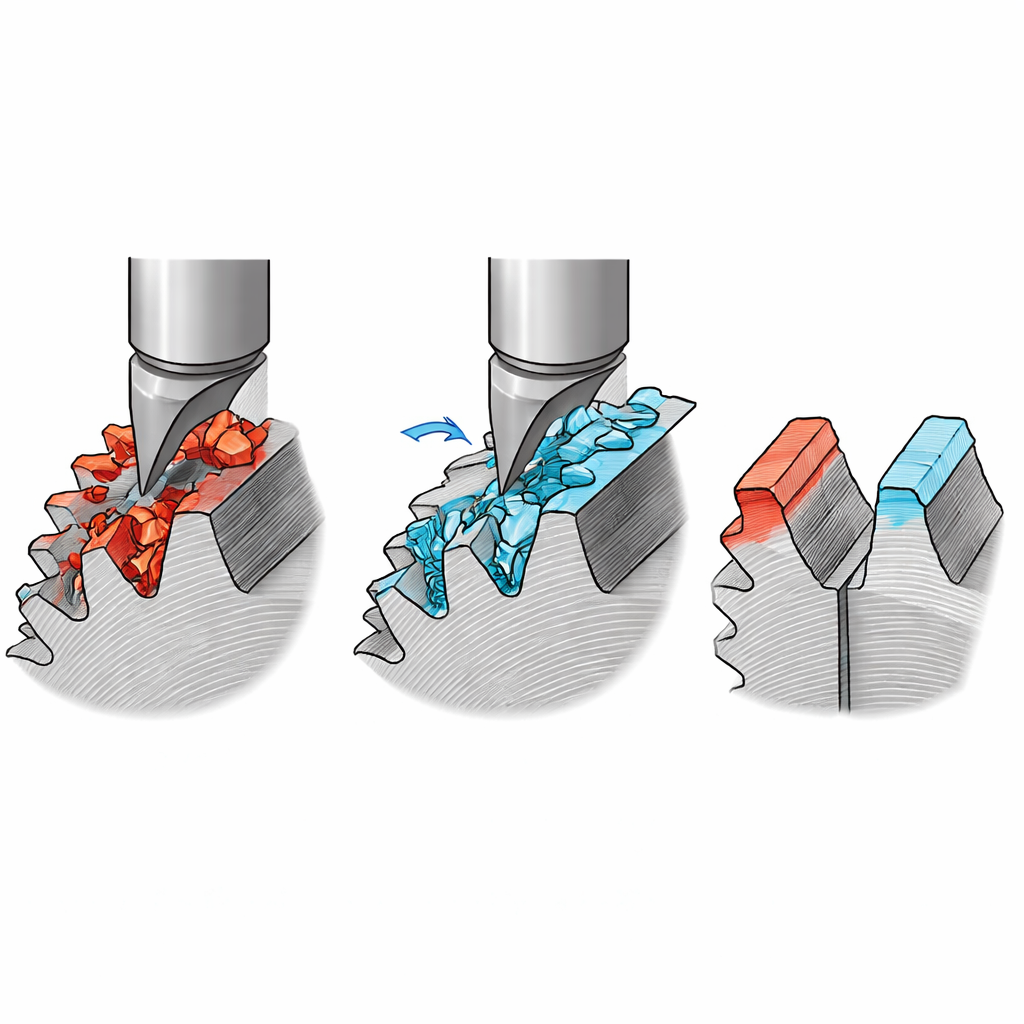
Cooler Tools and Gentler Stresses
By comparing the two tool shapes, the simulations revealed clear physical advantages for the curved design. The curved-face cutter greatly reduced fluctuations in cutting force and lowered peak temperatures at the tool–chip contact by roughly 15–20 percent. Heat was more evenly spread, avoiding sharp temperature gradients that can cause cracks and rapid wear. When the researchers examined the stress left in the finished gear teeth, they found that gears cut with the curved tool had smaller peak tensile stresses and a higher proportion of beneficial compressive stresses, spread more uniformly across the tooth surface. These smoother stress patterns are linked to better fatigue performance and longer gear life in service.
From Virtual Model to Real-World Gears
To confirm that the new design works outside the computer, the team manufactured indexable inserts with the curved front surface using advanced five-axis grinding and applied a hard coating. They then mounted these inserts on a cylindrical skiving cutter and machined real gears on an industrial machine tool. The cutting process was stable, with no signs of rubbing or collision. Measurements of the finished gears showed that tooth shape, spacing, and alignment met or exceeded industrial standards, and this was achieved with efficient cutting conditions.
What This Means for Future Machines
In everyday terms, the study shows that reshaping the working face of a gear-cutting tool can make the entire process calmer, cooler, and more predictable. The new cylindrical skiving tool with a uniform working angle maintains its accuracy after regrinding, avoids damaging interference with the gear, and leaves behind gear teeth with better stress patterns. For manufacturers, this translates into longer-lasting tools, fewer rejects, and more reliable gears in the cars, machines, and power systems we depend on.
Citation: Ji, J., Wang, P., Xue, R. et al. Design and cutting performance analysis of cylindrical gear skiving tool with uniform working rake angle. Sci Rep 16, 9510 (2026). https://doi.org/10.1038/s41598-026-40178-2
Keywords: gear skiving, cutting tool design, manufacturing processes, finite element simulation, gear machining