Clear Sky Science · en
Numerical investigation of co-flow jet integration to enhance the aerodynamic efficiency of airfoils used in wind turbine applications
Why this matters for clean energy
Modern wind turbines must squeeze as much power as possible from every gust of wind, yet their blades can lose performance when air flow "stalls" and peels away from the surface. This study explores a promising way to keep air attached to the blade using a built‑in recirculating jet of air, potentially allowing future turbines to generate more electricity, operate safely over a wider range of wind speeds, and make better use of renewable resources. 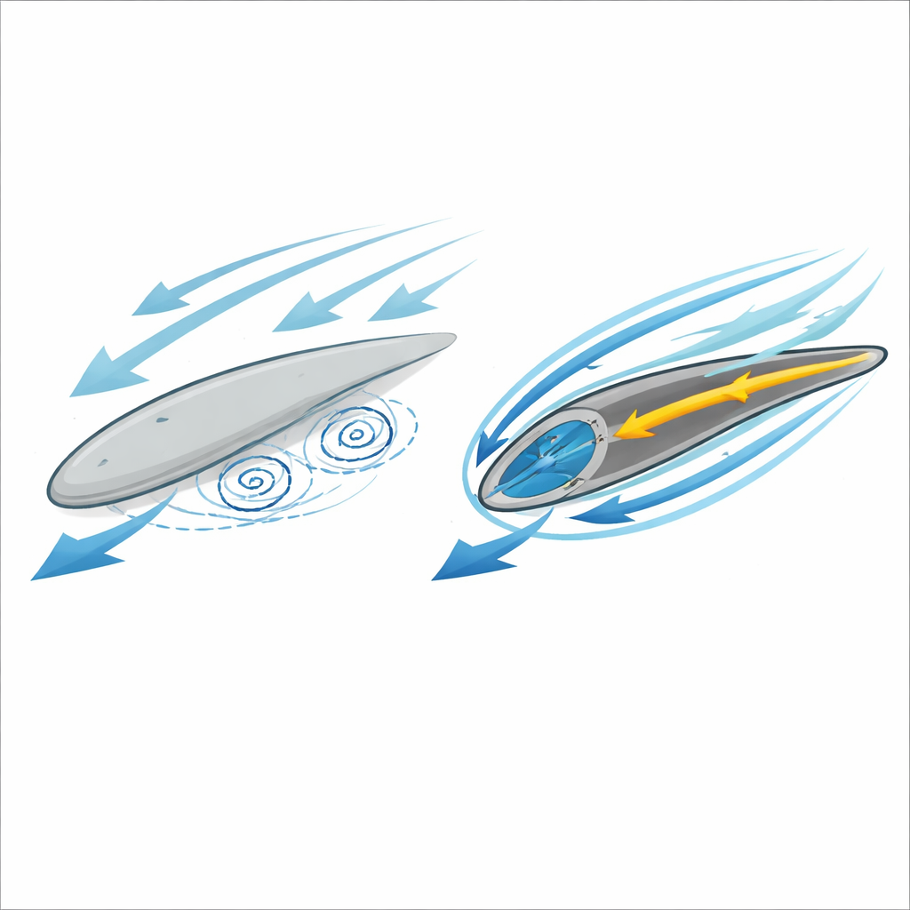
Keeping air glued to the blade
Wind turbine blades work like airplane wings: they rely on smooth, fast‑moving air over their upper surface to create lift. At high wind speeds or steep blade angles, this flow can separate, forming swirling vortices that slash lift and boost drag in a breakdown known as stall. Traditional fixes include reshaping the blade or adding small add‑ons that passively guide the flow, but these changes are limited and cannot adapt to changing winds. Active approaches, which use an external energy source to deliberately push or pull on the air, can offer bigger gains but are more complex. One such technique, the co‑flow jet, takes air from the back of the blade and blows it out again near the front, re‑energizing the thin layer of air that matters most for lift.
A blade with a built‑in breathing loop
The researchers focused on a widely used wind turbine blade cross‑section known as the S809 airfoil and equipped it with a co‑flow jet system. In their design, a narrow slot near the front of the blade injects air over the upper surface, while a longer slot closer to the rear sucks air back in. Inside the blade, an internal channel and small compressor complete the loop. Using computer simulations with a validated fluid‑flow model, they varied three key design choices: the angle at which air is injected near the front, the exact position of the suction slot near the rear, and how much air is recirculated through the system. They compared these modified blades to the original, untreated airfoil across a wide range of wind directions represented by angle of attack. 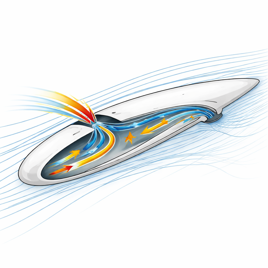
Finding the sweet spot for the jet
The team discovered that details of the geometry matter greatly. When the suction slot sits too far forward or backward, or when the jet emerges at a shallow angle, the flow control is much less effective. Their systematic search showed that the best layout places the suction slot at about 80 percent of the blade chord (measured from the front) and directs the injected air at a steep angle of about 78 degrees relative to the surface. With this combination, the simulations revealed that the once‑unstable flow stayed attached even at angles where the untreated blade had already stalled. Crucially, they also found that only a modest recirculated flow—about 2.5 percent of the wind passing through the rotor disk—is needed to unlock most of the benefit; pushing more air through the system yielded little additional improvement but would demand more compressor power.
How much better can a blade perform?
Under the optimal co‑flow jet settings, the simulated blade showed dramatic gains. At a demanding angle of attack of 20 degrees, the lift—the useful force that helps the turbine extract energy from the wind—rose by roughly 170 percent compared with the baseline blade, while drag was cut by about 53 percent. Together, these changes greatly improved the lift‑to‑drag ratio, a key measure of aerodynamic efficiency. The onset of stall was delayed from about 15 degrees to 20 degrees, increasing the stall margin by about one‑third. In practical terms, this means a turbine using such blades could safely operate at higher loading or in more turbulent winds before performance collapses.
Limits and safety considerations
The study also examined what happens if the co‑flow jet system suddenly stops working but the slots remain open. In this “turn‑off” scenario, the blade performed worse than the original solid airfoil: lift dropped by about 42 percent and stall arrived earlier, around 16 degrees. The empty channels and openings disturbed the flow instead of helping it. This result highlights an important engineering trade‑off: while co‑flow jets can strongly boost performance when powered, designers must also consider fail‑safe behavior and possibly include ways to close or bypass the slots when the system is inactive.
What this means for future wind turbines
Overall, the work shows that a carefully tuned co‑flow jet system can make a standard wind‑turbine blade section much more effective, especially under challenging wind conditions. By keeping air attached longer and delaying stall, such blades could capture more energy and run more stably without major changes to overall turbine design. The authors provide specific geometric guidelines—such as where to place the slots and how much air to recirculate—that can inform future experimental tests and commercial blade designs. If these ideas prove practical at full scale, they could help wind farms generate more clean power from the same winds, bringing us closer to a more sustainable energy mix.
Citation: Farghaly, M.B., El Kader, O.M.A., Alsharif, A.M. et al. Numerical investigation of co-flow jet integration to enhance the aerodynamic efficiency of airfoils used in wind turbine applications. Sci Rep 16, 9343 (2026). https://doi.org/10.1038/s41598-026-38769-0
Keywords: wind turbine blades, aerodynamic flow control, co-flow jet, stall delay, renewable energy efficiency