Clear Sky Science · en
Cutting parameter-tool material interaction on PcBN tool wear behaviour in ductile iron machining
Sharper Tools for Cleaner Cars
Modern car engines and electric drive motors rely on tough metal parts that must be machined with great precision and at low cost. This study looks at how advanced cutting tools made from a super‑hard material called PcBN behave when shaping ductile iron, a common material for crankshafts and motor housings. By understanding how these tools wear out, and how to choose their operating settings wisely, factories can make cleaner, more efficient vehicles while using less energy and replacing tools less often.
Why Tool Wear Matters on the Factory Floor
In automotive plants, parts such as crankshafts, engine blocks, and motor housings start as ductile iron blanks that must be cut to exact shapes. PcBN tools are attractive because they stay hard at high temperatures and can sometimes replace slower, grinding‑based finishing steps. However, when cutting ductile iron, these tools tend to wear out much faster than when cutting other cast irons, which drives up cost and downtime. The authors set out to understand, in a systematic way, how different PcBN tool recipes and cutting settings interact, and how to find a sweet spot that balances fast metal removal with long tool life.
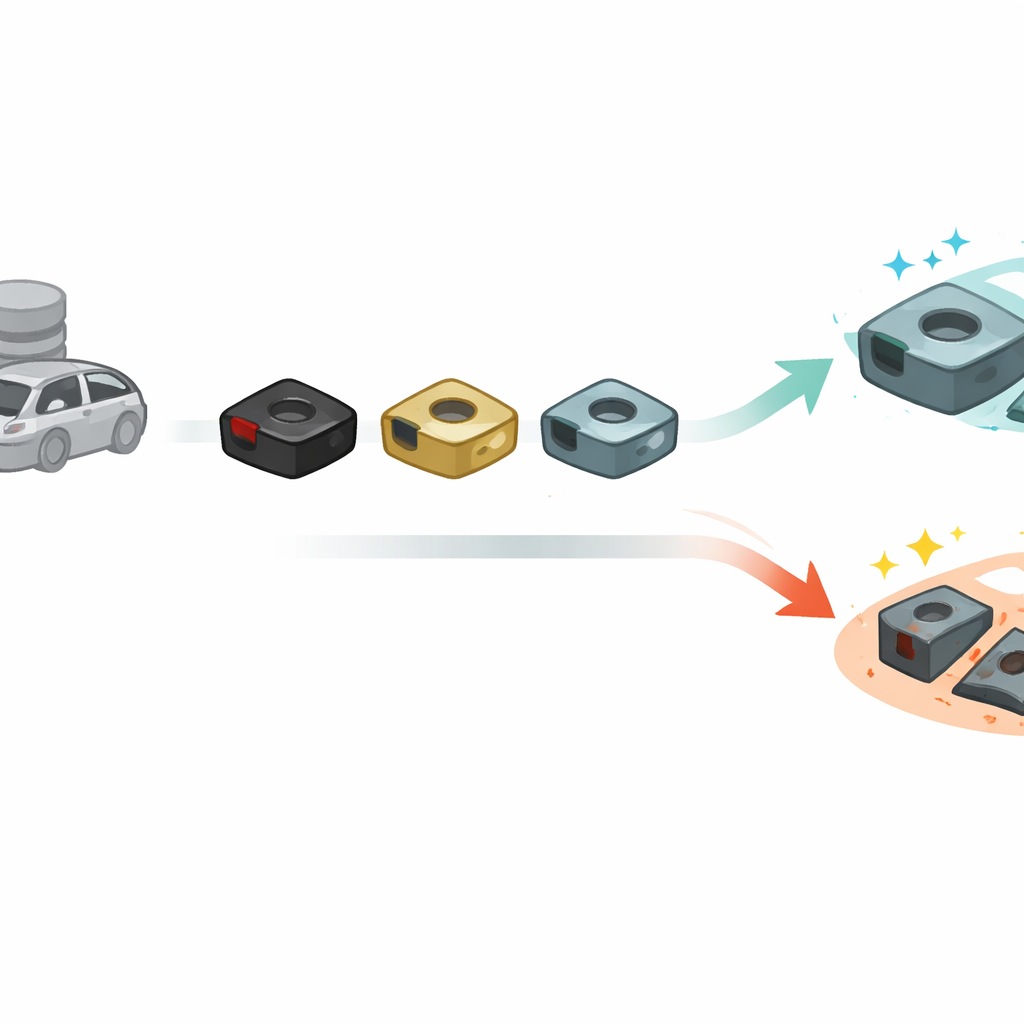
Comparing Three Super‑Hard Cutting Tools
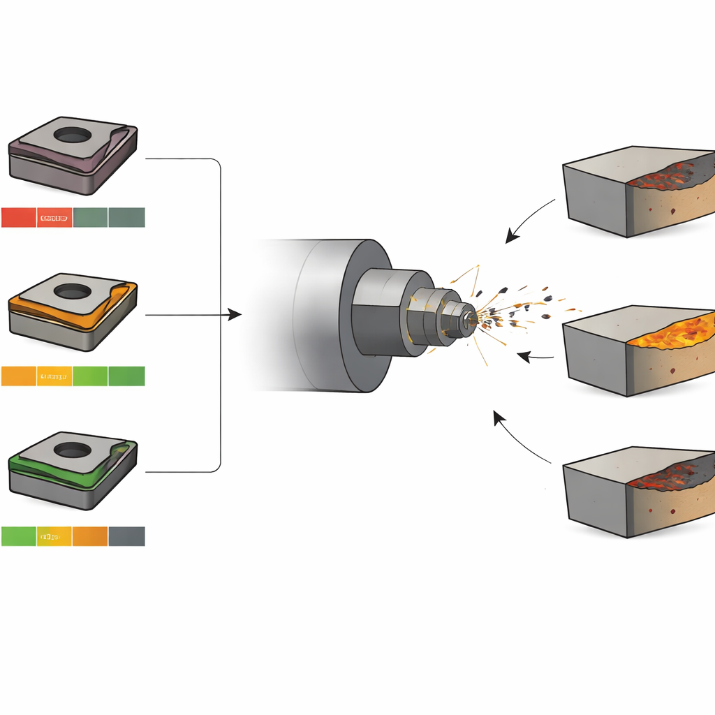
The team tested three kinds of PcBN inserts, all similar in shape but different inside. One tool used a metal binder, one used a ceramic‑like binder made of titanium carbide, and one had less of the super‑hard phase and more binder overall. They turned bars of high‑strength ductile iron on a CNC lathe, carefully varying cutting speed, feed rate, and depth of cut according to a planned test matrix. Every few hundred meters of cutting, they paused to measure the worn zone on the side of the tool until the wear reached an agreed limit. Microscopes and chemical analysis were then used to inspect the worn surfaces in detail, revealing grooves, craters, color changes, and traces of elements that had moved between tool and workpiece.
How and Why the Tools Wear Out
The study shows that three types of damage work together to wear out the tools. Abrasive wear comes from hard particles in the iron scratching and plowing the tool surface, especially at higher speeds. Chemical wear appears when the hot cutting zone causes reactions between the tool and surrounding air, forming oxides and causing key elements to leave the tool surface; in the most affected tool, oxygen content rose sharply while boron and nitrogen dropped. Adhesive wear occurs when tiny patches of iron briefly weld to the hot tool, then tear away, leaving pits and torn patches. The ceramic‑bonded tool with titanium carbide stood out: it showed milder craters and flank wear, and its binder formed a characteristic torn film that, while still damaging, was more controlled than in the other tools.
Finding the Sweet Spot in Cutting Settings
By analyzing tool life across many combinations of speed, feed, and depth, the authors converted cutting conditions into a single measure of metal removal rate and looked for patterns. Tool life generally fell as this rate rose, but not in a simple straight line. The titanium‑carbide‑bonded tool delivered the best overall performance in ductile iron, especially at medium cutting efficiency. An operating point around a moderate speed and modest feed and depth (producing about 15 cubic centimeters of metal removed per minute) gave a strong balance: long life with reasonably fast machining. In contrast, the tool with lower hard content sometimes lasted longest only at either very low or very high removal rates, making it better suited to niche conditions rather than everyday production.
From Test Data to Smart Predictions
To turn their findings into something factories can use, the researchers built simple mathematical models that link tool life to cutting speed, feed rate, and depth. These models can be fed with real‑time data from sensors on a machine, allowing the system to estimate how much life a tool had originally, how much has been used, and how much remains. The tool’s "health" is expressed as a percentage, and when that drops below a chosen threshold, the system can warn operators before failure causes poor surface quality or part scrap. Tests with varying cutting conditions showed that the prediction method tracks tool wear progression well enough to be practical on a production line.
What This Means for Everyday Manufacturing
For readers outside machining, the key message is that small changes in both tool recipe and operating settings can have large effects on reliability and cost. The work identifies a particular PcBN tool type and a window of cutting conditions that together give longer life and steady performance when shaping ductile iron parts. At the same time, it shows that simple, data‑driven models can watch tool wear in the background and recommend timely replacement. Taken together, these advances help car and motor makers cut tough metals faster, with fewer wasted parts and less energy, supporting cleaner and more efficient transportation.
Citation: Wang, P., Li, X., Jiu, Y. et al. Cutting parameter-tool material interaction on PcBN tool wear behaviour in ductile iron machining. Sci Rep 16, 9473 (2026). https://doi.org/10.1038/s41598-026-38314-z
Keywords: ductile iron machining, PcBN cutting tools, tool wear, cutting parameters, tool life prediction