Clear Sky Science · en
Design and validation of a high-speed rotor balancer based on influence coefficient method and dual-speed control
Keeping spinning machines healthy
From subway trains to factory robots, many of the machines that power modern life rely on parts spinning tens of thousands of times per minute. When those spinning parts are even slightly off-balance, they can shake, get noisy, waste energy, and wear out long before their time. This paper describes a new device that helps engineers detect and correct those tiny imbalances in high-speed electric motor rotors, aiming for quieter, more efficient, and longer-lasting machines.
Why balance matters for everyday technology
Inside an electric motor, the rotor is the part that spins. If its mass is not distributed evenly, each turn produces a small sideways pull, like a washing machine with clothes clumped to one side. At low speeds the effect may be mild, but at high speeds the forces rise sharply and can damage bearings, loosen parts, and reduce efficiency. Modern applications such as electric vehicles, drones, and precision tools increasingly use lightweight, high-speed rotors, which are especially sensitive to imbalance. The authors focus on permanent magnet DC motors and set out to build a balancer that can work safely and accurately at speeds close to 10,000 revolutions per minute.
A new tool for tuning spinning parts
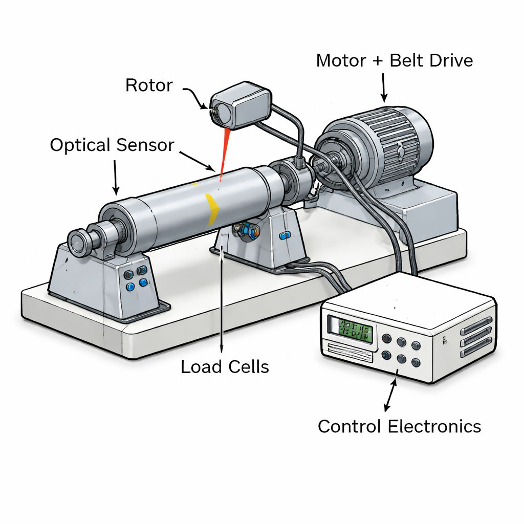
The team designed a two-plane balancing device, meaning it can correct imbalance at both ends of a rotor rather than treating it as a thin disk. The rotor rests on adjustable supports that suit different lengths and diameters, and it is driven by a DC motor through a belt-and-gear system. Two tiny load cells under the supports act as force sensors, while an optical sensor looks at a small mark on the rotor to track its angular position. Together, these sensors measure both how strongly the rotor shakes and at what angle that shaking occurs. Onboard electronics digitize these signals and send them to a computer, where dedicated software calculates how much mass to add or remove, and where, to bring the rotor into balance.
Smart control of speed and vibration
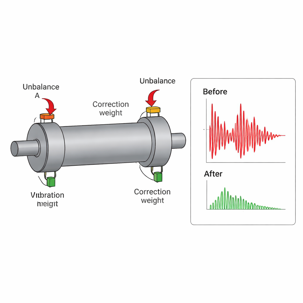
For balancing to be accurate, the rotor should be tested at or near the speed it will use in real service, because centrifugal forces grow with speed. To cover a wide range without overloading the drive motor, the device combines two methods of speed control: a mechanical gear-and-pulley system that selects a coarse speed band, and electronic control of the motor using pulse-width modulation (PWM) for fine adjustments. The researchers also apply an established technique called the influence coefficient method. In simple terms, they first measure how the rotor vibrates on its own, then repeat tests after attaching small known trial masses at different locations. By seeing how each trial mass changes the vibration at both supports, the software can solve a set of equations that reveals the size and angle of the correction masses needed in each balancing plane.
Testing the structure and the math
Spinning a rotor near 10,000 revolutions per minute can excite natural vibration modes of the test rig itself, which would blur the measurements. To avoid this, the authors used engineering simulation software to model the balancer’s structure, mesh it into many small elements, and compute its natural frequencies and vibration shapes. The lowest natural frequency they found was about 216 hertz, comfortably above the roughly 167 hertz associated with 10,000 revolutions per minute, so the device should not resonate in its working range. They then performed motion simulations with deliberately unbalanced rotors of different masses. At each step they applied the same influence coefficient procedure as in real tests, computed correction masses, and “installed” them in the virtual model. The simulated vibration levels dropped markedly, confirming that the equations and software logic work as intended.
Handling real-world imperfections
In practice, no setup is perfect: even a small height difference between the two force sensors can tilt the rotor and mix unwanted forces into the readings. The authors studied this by introducing controlled misalignments in their simulations and repeating the balancing procedure. They found that as the height error grew, the calculated correction masses deviated more from the ideal values. By examining how fast this error increased, they concluded that keeping the two sensor planes aligned within about a quarter of a millimeter keeps the mass error within an acceptable range for high-speed balancing. This gives practical guidance for assembling and maintaining the device in workshops and labs.
Smoother rotors, longer-lasting machines
Overall, the work delivers a compact, high-speed rotor balancer that combines precise sensors, flexible speed control, and a proven balancing algorithm in a single system. Structural simulations show it can run safely up to 9500 revolutions per minute, while motion studies demonstrate that it can compute and apply effective correction masses, even for lightweight rotors. For non-specialists, the key takeaway is that this kind of tool makes it easier to tune spinning parts so they run smoothly, which in turn means quieter devices, better energy use, and longer service life for the many machines that rely on electric motors.
Citation: Gharehcheloo, P.K., Saberi, F.F. & Shamshirsaz, M. Design and validation of a high-speed rotor balancer based on influence coefficient method and dual-speed control. Sci Rep 16, 7752 (2026). https://doi.org/10.1038/s41598-026-38071-z
Keywords: rotor balancing, electric motors, vibration, high-speed machinery, condition monitoring