Clear Sky Science · en
Case study report on design, manufacturing and digital representation of a DED-Arc steel node for construction
Why this new steel joint matters
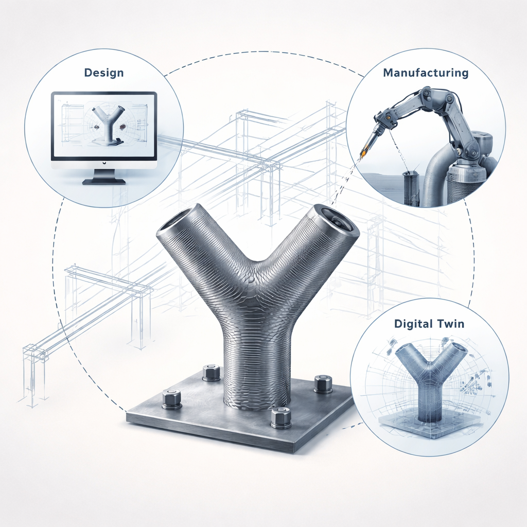
Modern buildings are becoming more daring in shape and scale, but the metal parts that hold them together are often still made with old, labor‑intensive methods. This paper follows the full journey of a custom Y‑shaped steel node—from computer design, to robotic 3D welding, to a rich digital model that predicts how it will behave in service. For anyone interested in how digital fabrication and “virtual twins” are changing construction, this case study offers a concrete glimpse of the near future.
From solid plates to printed steel
In conventional steel construction, complex joints are typically cut from many flat plates and then carefully welded together, or cast in a mold. Both routes are slow, waste material, and limit how freely architects can shape structures. The researchers instead use a process called DED‑Arc, a form of metal 3D printing that feeds a steel wire into an electric welding arc. Layer by layer, the wire is melted and deposited until the part takes shape. This approach is especially attractive for one‑off, heavy components like building nodes, because it can follow almost any geometry while cutting down on manual work.
Building a challenging Y‑shaped joint
To probe the possibilities and limits of this method, the team chose a particularly awkward test piece: a Y‑shaped node that starts as a square column at the base and splits into two round branches. Such a shape is difficult to make with plates, and even for 3D welding it poses problems. Overhanging regions can droop, and the robot’s torch risks colliding with the growing part. The authors show how they first rethought the design and manufacturing strategy, splitting the node into a main body and a bridge section, and using an eight‑axis setup with a tilt‑turn table so that each new weld bead could be laid in a favorable position rather than fighting gravity.
Smart slicing and careful robot motion
Turning the 3D design into thousands of weld paths is not trivial. A simple “stack of flat layers” would leave some areas under‑supported and produce rough surfaces. Instead, the team used an equidistant slicing method that automatically adds more, thinner layers where the surface tilts, keeping the build height per pass nearly constant. They then planned the robot’s motion so the welding torch stayed almost tangent to the surface and, where possible, printed in a vertical position that stabilizes the molten pool. Even so, the final bridge closure required manual fine‑tuning of the paths, and small distortions of the base plate slowly amplified as the structure grew—lessons that point to the need for stiffer fixtures and more adaptive control.
Giving the part a living digital twin
Beyond simply building the node, the study shows how to give it a detailed digital “shadow,” or Digital Twin. During planning and printing, the researchers stored the designed geometry, each tool path, and the process signals from the welding power source. After fabrication, they 3D‑scanned the finished node and aligned the scan back to the original design using mathematical matching techniques. This unified data model links “as‑designed,” “as‑built,” and “as‑printed” views of the same object in one coordinate system, so that every spot on the surface can be tied to the local build direction, heat input, and final shape.
Seeing hidden stresses before the building is built
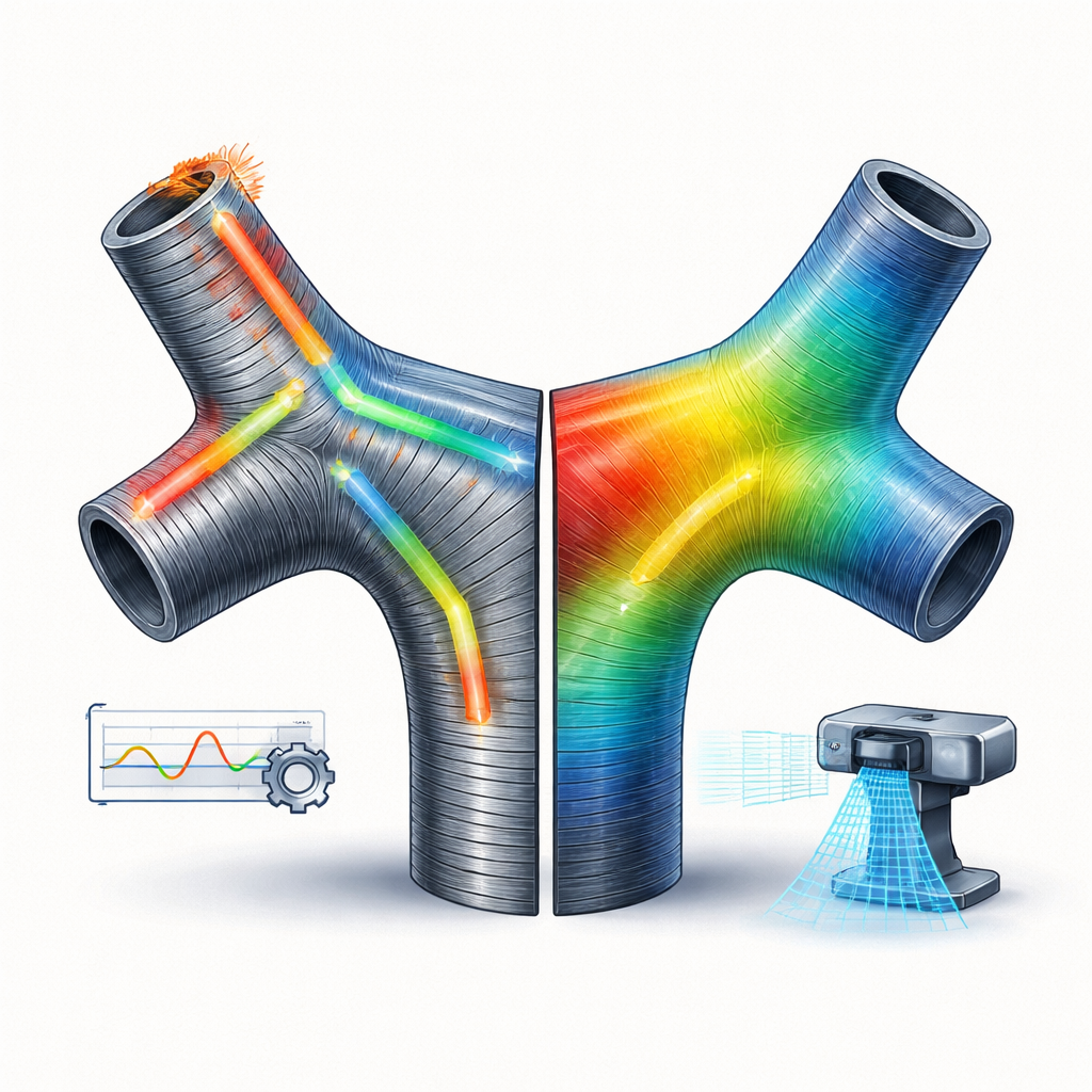
With this digital twin in place, the team ran advanced computer simulations to see how the node would carry load. They fed in the print‑path directions and an anisotropic material model—one that recognizes that printed steel is not equally strong in every direction. The analysis revealed strong stress concentrations between the two arms and at their connections, and showed how manufacturing choices, such as changing the print direction in the bridge, alter the stress pattern. Because large construction parts are usually unique, it is impractical to test full‑scale prototypes. A well‑calibrated digital twin that embeds process data therefore becomes a powerful design tool, helping engineers aim for “first‑time‑right” parts instead of expensive trial‑and‑error.
What this means for future buildings
In plain terms, the study demonstrates that it is now possible to 3D‑print complex steel joints for buildings while tracking every step in enough detail to predict how the finished part will behave. The authors argue that future systems will go further, using real‑time 3D scanning and automatic path adjustments to correct deviations as they arise. If such closed‑loop digital workflows become standard, designers will gain more freedom in shaping structures, manufacturers will waste less material and time, and the custom metal pieces inside tomorrow’s buildings will be safer and more reliable—even when no physical prototype is ever built.
Citation: Müller, J., Jahns, H., Müggenburg, M. et al. Case study report on design, manufacturing and digital representation of a DED-Arc steel node for construction. Sci Rep 16, 3263 (2026). https://doi.org/10.1038/s41598-026-37315-2
Keywords: metal 3D printing, steel construction, digital twin, wire arc additive manufacturing, structural nodes