Clear Sky Science · en
DEM analysis of boundary effects in simple shear tests
Why the shape of the boundary matters
When engineers test how soils or grains behave under stress, they often rely on a device that squeezes and slides a short cylinder of material between two plates. These tests are used to design foundations, retaining walls, and even to understand natural hazards like landslides and earthquakes. But there is a catch: if the grains slip along the top and bottom plates instead of moving together, the test may give a misleading picture of how the material really behaves underground. This study asks a deceptively simple question: can we change the design of those plates so that the grains are forced to share the load more realistically, without making the experiments or computer models unmanageably complex?
From smooth plates to patterned surfaces
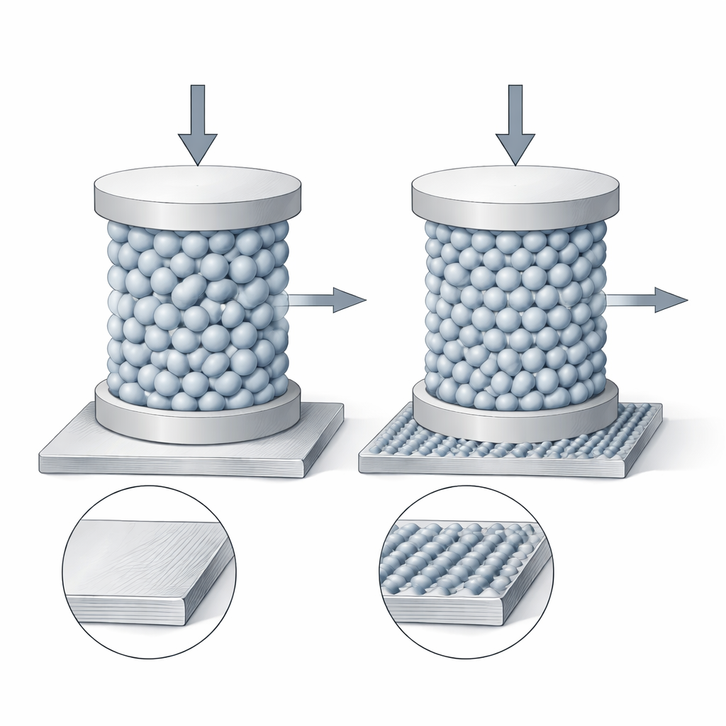
Traditional devices use flat plates with roughened surfaces to grab the grains and transmit shear — the sideways force that makes layers slide past one another. In computer simulations, researchers have often taken a shortcut by keeping the plates flat but assigning them an unrealistically high friction value, effectively telling the software that the plates are extremely rough. The authors of this paper tested a different approach. They compared four boundary designs: completely flat plates and three types of plates covered with raised patterns — long ribs, large pyramids, and small pyramids. Both real experiments and detailed computer simulations were run on samples made of steel spheres, a simple stand-in for more complex soils.
Watching grains move, not just forces
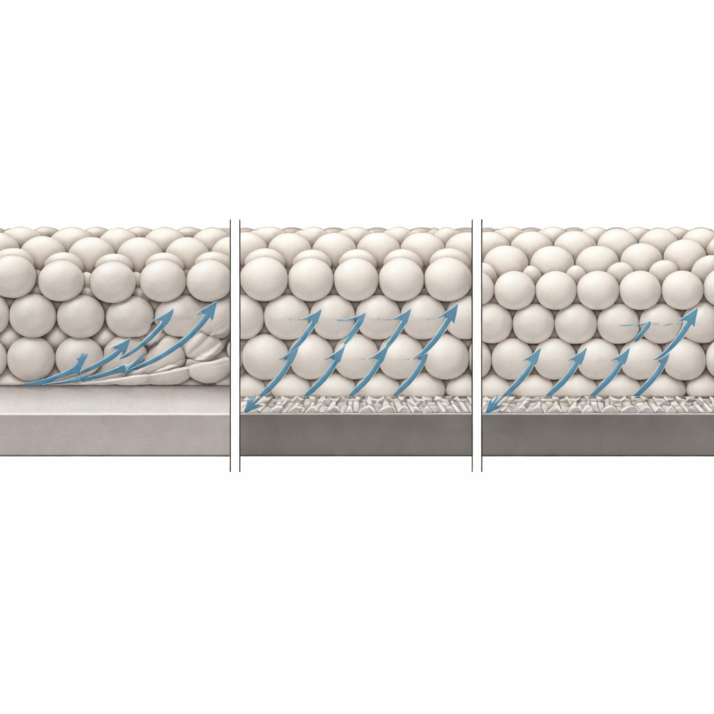
Instead of looking only at how much total force each sample could carry, the team examined what happened layer by layer inside the grain assembly. They tracked how tightly the grains packed near the boundaries, how they moved horizontally and vertically, and how much they rotated as shear was applied. With patterned plates, the raised features pushed into the sample and encouraged grains at the top and bottom to lock together with the rest of the specimen. This created a nearly uniform “shear profile,” where displacement increased smoothly from the fixed plate to the moving plate. In contrast, with flat plates, many grains near the boundaries simply rolled and slipped, so the middle of the sample did not experience the clean, even shearing that the test is supposed to produce.
Matching laboratory tests and computer models
The researchers carefully built computer models that mirrored their laboratory setup, using the same grain sizes, densities, and plate geometries. They found that simulations using ribbed or pyramid plates reproduced the overall stress–strain curves and volume changes measured in the physical tests, even though small differences in packing density and height measurements remained. Importantly, when they modeled flat plates with artificially high friction — a common numerical shortcut — the overall curves did not look dramatically wrong, but the internal grain motions did. The grains formed wedge-shaped zones of movement and excessive rolling at the boundaries, more like a sliding block failure than the intended simple shear. This shows that relying on surface-level agreement between experiments and simulations can hide very different and less realistic internal behaviors.
Balancing accuracy and computing cost
Adding ribs or pyramids to the plates makes the model boundaries more complicated, which could, in principle, slow down simulations. The team quantified this cost by tracking how long it took to reach a given amount of shear in their discrete element models. While the patterned plates did require more tiny surface elements to represent their shape, even the most complex small-pyramid design increased computing time by only about 6 percent. For the simpler ribbed plates, the extra time was even smaller. In other words, the price of greater realism in the boundary conditions is modest compared with the risk of misrepresenting how the grains actually transmit shear through the sample.
What this means for real-world testing
For engineers and scientists who depend on simple shear tests, this work delivers a clear takeaway: the geometry of the top and bottom plates strongly controls whether the test truly represents a uniform shearing process. Flat plates, even when made “rough” in the computer by cranking up friction, can allow grains to roll and slip in ways that hide the real failure patterns. Plates with ribbed or pyramid-shaped projections interlock with the grains, ensuring that shear is carried through the entire specimen and that experiments and simulations are more directly comparable. Because such plates can be produced with modern 3D printing or straightforward machining, the authors recommend adopting projection-based boundaries in both laboratory devices and numerical models to obtain more reliable and physically meaningful results.
Citation: Guo, J., Sun, M., Bernhardt-Barry, M.L. et al. DEM analysis of boundary effects in simple shear tests. Sci Rep 16, 8684 (2026). https://doi.org/10.1038/s41598-026-37235-1
Keywords: simple shear test, granular materials, discrete element method, boundary conditions, shear transmission