Clear Sky Science · en
Modeling and experimental study of cutting forces of a variable pitch ball-end cutter in five-axis milling
Why smoother metal cutting matters
From jet engines to spacecraft, many modern machines depend on metal parts with flowing, curved shapes and thin walls. These parts must be cut from tough alloys, yet any tiny vibration or excess force during machining can leave marks, weaken the material, or shorten its life. This study tackles a practical question at the heart of advanced manufacturing: how can we predict the forces acting on a special type of cutting tool—a variable-pitch ball-end mill—so that these complex parts can be cut faster, more accurately, and with less risk of damaging chatter?
A new look at a familiar cutting tool
Ball-end mills are common tools whose rounded tips can trace out smooth surfaces that flat tools cannot easily reach. But this round shape also makes their behavior tricky to predict. The cutting speed changes from zero at the very tip to a maximum at the sides, and in multi-axis machines the tool constantly tilts and swivels. On top of that, this study focuses on “variable-pitch” tools, where the spacing between neighboring cutting edges is intentionally made uneven. This irregular spacing helps to break up vibrations, but it also complicates the way forces build up during cutting. To handle this, the authors build a detailed mathematical model that links the geometry and motion of such a tool to the forces it generates in real machining.
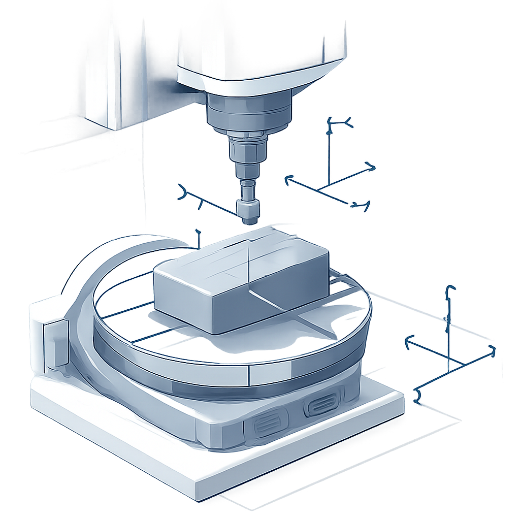
Mapping the invisible contact between tool and metal
At the core of the work is a careful description of how the cutting edge actually meets the metal. The authors define several coordinate systems: one attached to the machine, one to the workpiece, one to the tool, and one that follows the feed direction. Using these frames, they describe exactly where each tiny segment of the cutting edge is in space at any moment. Instead of trying to track a fully three-dimensional, moving contact zone directly—which would be extremely complex—they project the engagement area onto a flat plane perpendicular to the tool’s axis. This clever simplification lets them find, for each microscopic piece of the cutting edge, the angles at which it enters and leaves the material and how deeply it bites in.
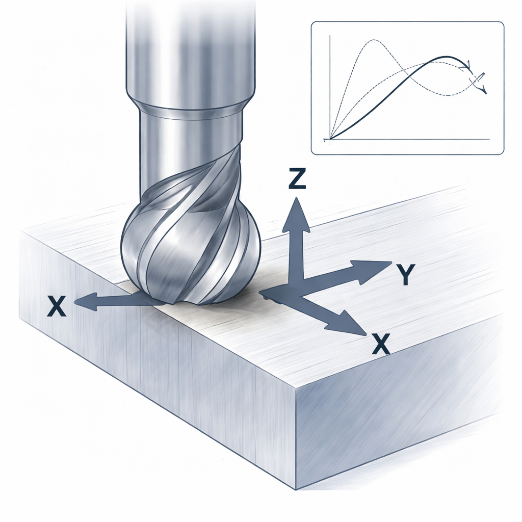
Building forces from tiny pieces
Once the contact is known, the study treats the cutting edge as a stack of very small elements along the tool’s axis. For each element, the model calculates how thick the chip of metal will be and how long that piece of edge is. The local cutting force is then split into two parts: one from shearing the metal and one from a smaller “ploughing” effect as the edge rubs and pushes. These elemental forces are expressed along three directions—tangential, radial, and axial—then converted into the tool’s own X, Y, and Z directions and summed over the whole cutting edge. Because variable-pitch tools do not share the same feed conditions on each tooth, the model also adjusts the chip thickness tooth by tooth, capturing how irregular spacing reshapes the force pattern and helps to damp vibrations.
From equations to real titanium chips
A model is only useful if it matches reality, so the team conducted controlled milling tests on titanium alloy plates—a material widely used in aerospace for its strength and heat resistance. Using a four-tooth variable-pitch ball-end cutter on a five-axis machine, they measured forces in three directions with a precision force sensor while varying cutting depth and feed per tooth. Instead of the usual full-slot cuts, they used shallow passes resembling real finishing operations, where often only one tooth is cutting at a time. From these measurements, they extracted average forces for each individual tooth and used them to calibrate the unknown cutting-force coefficients in their equations, allowing the model to adapt to the actual behavior of the tool and material.
How well the predictions hold up
With the calibrated coefficients in hand, the authors ran simulations using the same cutting conditions as the experiments and directly compared predicted and measured forces. The wave shapes, peaks, and valleys in all three directions lined up closely, and a detailed error analysis showed that the mismatch was at most 6.74 percent. This level of accuracy is high enough to support practical tasks such as choosing safe cutting parameters, avoiding chatter, and optimizing tool design. The study also shows how changing the tool’s tilt angles reshapes the contact area and shifts where along the ball end the load is carried, providing a more intuitive picture for process planners.
What this means for future machining
For non-specialists, the takeaway is that this work offers a science-based way to predict what a complex cutting tool will do before metal is actually cut. By combining geometric insight, physics of chip formation, and targeted experiments, the authors created a force model tailored to variable-pitch ball-end mills in multi-axis finishing. This can help manufacturers push machines harder without sacrificing surface quality, shorten trial-and-error setup, and design tools and tool paths that keep vibrations in check. In the long run, such models support more reliable production of lightweight, high-performance parts that go into aircraft, turbines, and other demanding technologies.
Citation: Tian, W., Zhou, J., Ren, J. et al. Modeling and experimental study of cutting forces of a variable pitch ball-end cutter in five-axis milling. Sci Rep 16, 6541 (2026). https://doi.org/10.1038/s41598-026-36982-5
Keywords: five-axis milling, variable-pitch cutters, ball-end milling, cutting force modeling, titanium machining