Clear Sky Science · en
Suppressing loop current of shielded loops at fundamental resonance
Making MRI Scans Work Together Better
Magnetic resonance imaging (MRI) machines rely on arrays of small metal rings, called coils, to pick up faint signals from inside the body. As scanners become more powerful and coil arrays more complex, a hidden problem grows: unwanted electrical currents can flow in these rings, quietly degrading image quality and even creating safety concerns. This study tackles that problem for a popular but tricky coil design known as the shielded loop, and shows how to almost completely shut down those unwanted currents using simple, well-chosen components.
Why Loops Matter in MRI
In an MRI scan, one set of hardware transmits strong radio waves that disturb atomic nuclei in the body, while another set of coils “listen” as those nuclei relax and emit tiny radio signals. These listening elements are often loops of wire. In recent years, shielded loops made from coaxial cable have attracted interest because they are flexible, less sensitive to being bent or pressed against the body, and tend to interfere less with one another than traditional wire loops. When tuned to what engineers call their fundamental resonance, these shielded loops behave like very high-impedance detectors, which is helpful for building dense arrays that can hug the anatomy.
When Helpful Signals Become Harmful Noise
In a single coil used alone, the current that flows during reception is simply part of the detection process. In an array, however, currents in one loop can induce currents in its neighbors, blurring the individual sensitivity patterns that are needed for sharp images and advanced reconstruction methods. During the powerful transmit phase, strong fields can also drive large currents in receive-only loops, distorting the spin dynamics inside the patient and potentially heating tissue. Traditional loop coils solve this by arranging overlaps and by attaching circuits or amplifiers that present a high resistance to current flow. For shielded loops at resonance, though, it has not been clear how best to stop the current; simply shorting the output terminals, an intuitive approach, turns out to be far from optimal.

Rethinking How Shielded Loops Behave
The authors show that, despite appearances, a shielded loop is not just a standard resonant circuit in disguise. Instead of trying to make the loop see a very high resistance, the key is to cancel the reactive part of the loop’s electrical response at its output and then present it with a low, well-controlled resistance. They provide a general recipe: first, conceptually “disconnect” the inductive ring inside the shielded loop in a mathematical model to find the net reactance seen at the output. Then, choose a component at the output whose reactance is equal in size but opposite in sign, and whose internal losses are small. Under many practical conditions, this component turns out to be, or closely mimic, a simple inductor.
A Simple Rule for Complex Coil Designs
Shielded loops can be built with one or more small breaks, or gaps, around the ring, and may or may not include extra tuning capacitors. For loops without added tuning parts and with evenly spaced gaps, the authors derive a remarkably simple rule: the inductor that best suppresses the loop current should have an inductance equal to the inductance of an equivalent plain wire loop, divided by the number of gaps. They also show how to estimate that base inductance from the loop’s size and wire thickness. For more elaborate designs, including loops with tuning capacitors or uneven gaps, their general method of removing the internal inductor in the model and matching the reactance still works to determine the right output component.
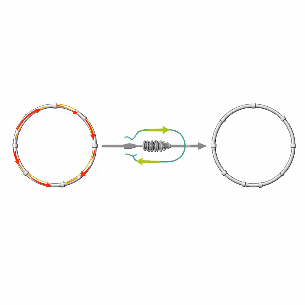
Putting the Theory to the Test
To check their ideas, the researchers built five different shielded loops from standard coaxial cable, with one, two, or three gaps and with or without tuning capacitors. They measured the actual currents flowing on the outer surface of the cable using a carefully calibrated double-loop magnetic probe and compared those results to circuit simulations. When they terminated the loop outputs with inductive elements chosen according to their guidelines, the unwanted loop currents around resonance dropped by an extra 31 to 36 decibels compared with the simple shortcut of shorting the outputs—a reduction by more than a factor of one thousand in amplitude. The measured optimal inductances matched their predictions to within about seven percent, even though real-world construction imperfections and cable details were not perfectly modeled.
What This Means for Future MRI Coils
For non-specialists, the takeaway is that the authors have turned a subtle electrical problem into a clear design rule. By treating shielded loops correctly—not as generic resonant circuits but as physical loops with a specific relationship between their size and a matching inductor—engineers can build coil arrays that stay quiet when they should, listen cleanly when needed, and disturb the patient’s tissue less during powerful transmit pulses. This should make it easier to design flexible, wearable, and densely packed MRI detectors that deliver higher-quality images and more reliable performance without adding complexity to the scanner hardware.
Citation: Wang, W., Jepsen, R.A., Sánchez-Heredia, J.D. et al. Suppressing loop current of shielded loops at fundamental resonance. Sci Rep 16, 8400 (2026). https://doi.org/10.1038/s41598-026-36956-7
Keywords: MRI coils, shielded loop, high-impedance coil, decoupling, loop current suppression