Clear Sky Science · en
Evaluation of electric vehicle performance using driving cycle clustering based on motor-inverter losses and efficiency
Why this study matters for electric cars
Electric cars promise cleaner cities and lower carbon emissions, but how efficiently they turn battery energy into motion depends on more than just the motor. This study looks inside the electric drivetrain to see how both the motor and the power electronics that feed it waste or save energy under real driving conditions. By condensing thousands of seconds of stop‑and‑go traffic into just a handful of key situations, the authors show how engineers can design more efficient, longer‑range electric vehicles without drowning in computation.
From roads and traffic to forces and speeds
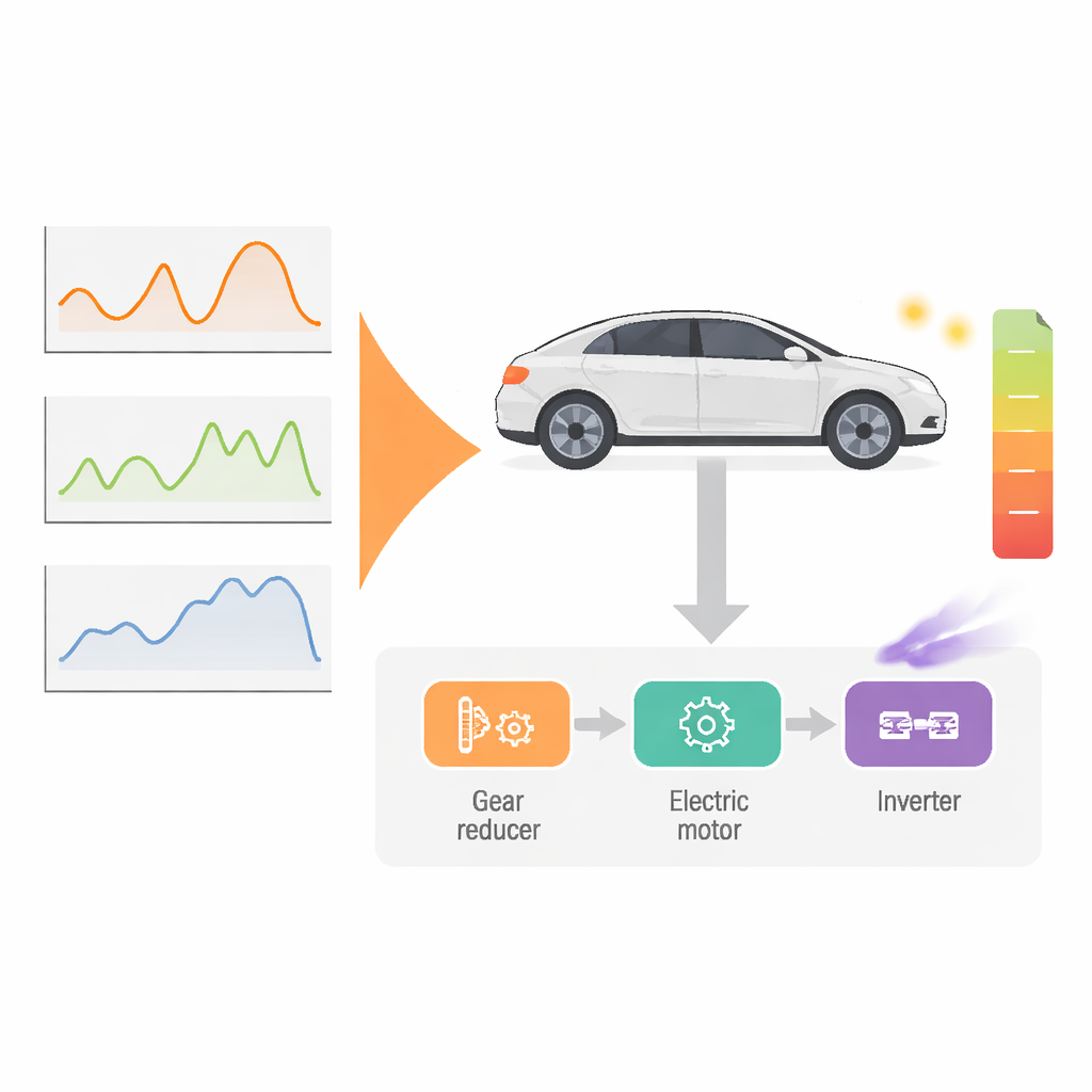
The researchers begin at the road level, using three standard speed profiles that carmakers already rely on for testing: European, worldwide, and U.S. city‑style driving cycles. These are time histories of how fast a car goes, how often it stops, and how hard it accelerates. From these curves, a vehicle model computes the forces at the wheels and then the torque and speed that the electric motor must deliver through a fixed gear. In this way, every second of driving is translated into a point on a torque–speed map, revealing where in its operating range the motor actually spends its time and energy.
Compressing thousands of moments into a few key ones
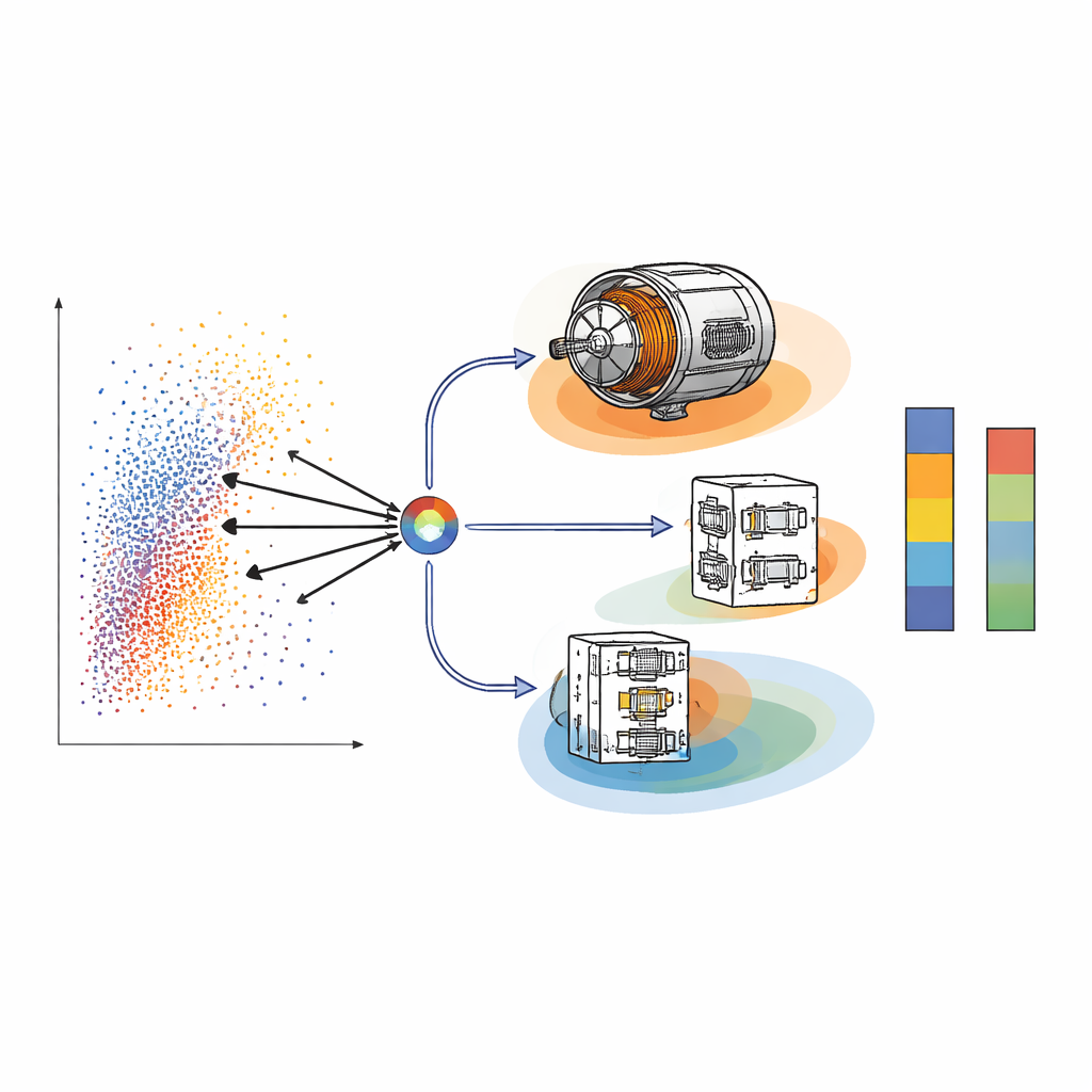
Simulating a sophisticated motor design at every single torque–speed point would take days or weeks of computer time. To avoid this, the study applies data‑mining tools. First, a common clustering method groups similar operating points together. Then, an energy‑aware refinement, called the Energy Centre of Gravity approach, makes sure the chosen “representative points” are not just typical, but also sit where most of the energy is actually used. Each representative point is given a weight based on how often it occurs and how much energy it draws, so a small set of points can stand in for an entire trip while preserving the true energy picture.
Peering inside the motor and its electronic heartbeat
With these representative points in hand, the authors turn to detailed motor simulations. They study an interior permanent magnet motor, a popular choice for electric cars because it packs high torque and efficiency into a compact package. Using finite element analysis, they map how magnetic fields, copper windings, and steel cores behave over a range of current settings. A control strategy known as “maximum torque per ampere” is used to find, for each operating point, the current combination that delivers the needed torque with the least electrical effort. From these simulations they extract key loss sources: heating in the copper windings and magnetized steel that saps energy and must be removed by cooling systems.
Comparing electronic “valves” that feed the motor
The study then adds the effect of the inverter, the box of fast electronic switches that converts battery direct current into the three‑phase currents the motor needs. Two modern inverter technologies are compared: one based on IGBT switches and another on SiC MOSFET switches. Using models built from manufacturer data, the authors calculate both conduction losses (energy lost whenever current flows) and switching losses (bursts of energy wasted each time the devices turn on and off). They feed the resulting current waveforms into the motor simulations, revealing how the sharp, pulsed currents from real inverters introduce extra ripples in torque and additional magnetic losses compared with an ideal smooth supply.
What this means for range, efficiency, and computing time
Across all three driving cycles, the clustering approach reproduces full‑cycle motor efficiency within about two percent, while cutting detailed simulations from tens of hours down to around ten minutes per cycle for the motor alone. When inverter behavior is included, total losses rise noticeably, and overall drivetrain efficiency drops by a few percentage points compared with the idealized case. Yet the SiC MOSFET‑based inverter consistently wastes less energy than the IGBT‑based one, thanks to lower switching losses, making it especially attractive for vehicles that see frequent speed changes. To a layperson, the main message is that both the motor and its electronic “faucet” must be designed together, and that smart data reduction lets engineers test many ideas quickly. By capturing the most important driving situations and modeling the joint motor‑inverter system, this work offers a practical path toward electric cars that go farther on the same battery charge without requiring impractical amounts of computing power.
Citation: Abdelali, K., Bendjedia, B., Rizoug, N. et al. Evaluation of electric vehicle performance using driving cycle clustering based on motor-inverter losses and efficiency. Sci Rep 16, 8040 (2026). https://doi.org/10.1038/s41598-026-36663-3
Keywords: electric vehicle efficiency, traction motor design, power electronics inverter, driving cycle analysis, energy losses