Clear Sky Science · en
Research on geometric parameter quantification of rail rolling contact fatigue crack damage based on 2D optical image
Why tiny rail cracks matter to everyone
High-speed trains rely on rails that can safely withstand millions of wheel passes. Yet the same repeated rolling contact that enables fast, smooth travel slowly grinds away at the steel, creating tiny fatigue cracks that can grow into serious defects, rail breaks, and even derailments. Inspecting thousands of kilometers of track thoroughly and quickly is extremely difficult. This study presents a new way to spot and measure these dangerous cracks more accurately, using a combination of regular camera images and heat-based sensing, paving the way for safer and more efficient rail networks worldwide. 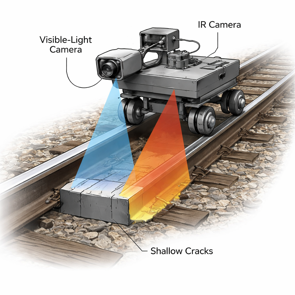
How rails are checked today—and why it’s not enough
Railway engineers already use an arsenal of non-destructive testing tools to hunt for flaws: ultrasound, magnetic methods, eddy currents, and laser and video systems. Each has strengths but also blind spots. Some methods struggle with very small cracks, some lose sensitivity at higher speeds, and others cannot easily tell how deep a crack goes. For rolling contact fatigue, where many small cracks spread at angles from the rail surface, it is especially hard to measure key geometric parameters—length, depth, and width—precisely and quickly. That missing information makes it difficult to decide when a track section truly needs repair or replacement.
Blending sight and heat to see cracks more clearly
The researchers designed a rail inspection system that fuses two kinds of images: standard 2D optical pictures and infrared thermal images created by eddy current pulsed thermography. In this technique, an induction coil briefly heats the rail surface with an alternating current, causing tiny temperature changes that are captured by an infrared camera. Cracks disturb how electric currents flow and how heat spreads, leaving subtle but informative patterns on the temperature map. At the same time, a high-resolution industrial camera records visible images of the rail head. A tailored image-processing and neural-network pipeline first finds and classifies surface defects in the optical images, then aligns and merges them with the thermal maps so that both views describe the same crack.
A new mathematical lens on crack shape
Simply overlaying pictures is not enough to turn faint image differences into reliable measurements. The team therefore introduced a mathematical quantity they call the “Poisson reconstruction degree,” which is based on solving a Poisson equation that links gradients and intensity changes in the fused images. In more accessible terms, the method looks at how quickly the image values change across a crack in both the optical and thermal data and distills that into a single number that tracks with crack size. By statistically analyzing this measure for many artificial cracks of known length, depth, and width, the authors showed that the Poisson reconstruction degree changes in a nearly linear way with these geometric parameters. That means it can be used like a calibration ruler: once the curve is known, the image-based value directly translates into a physical crack size. 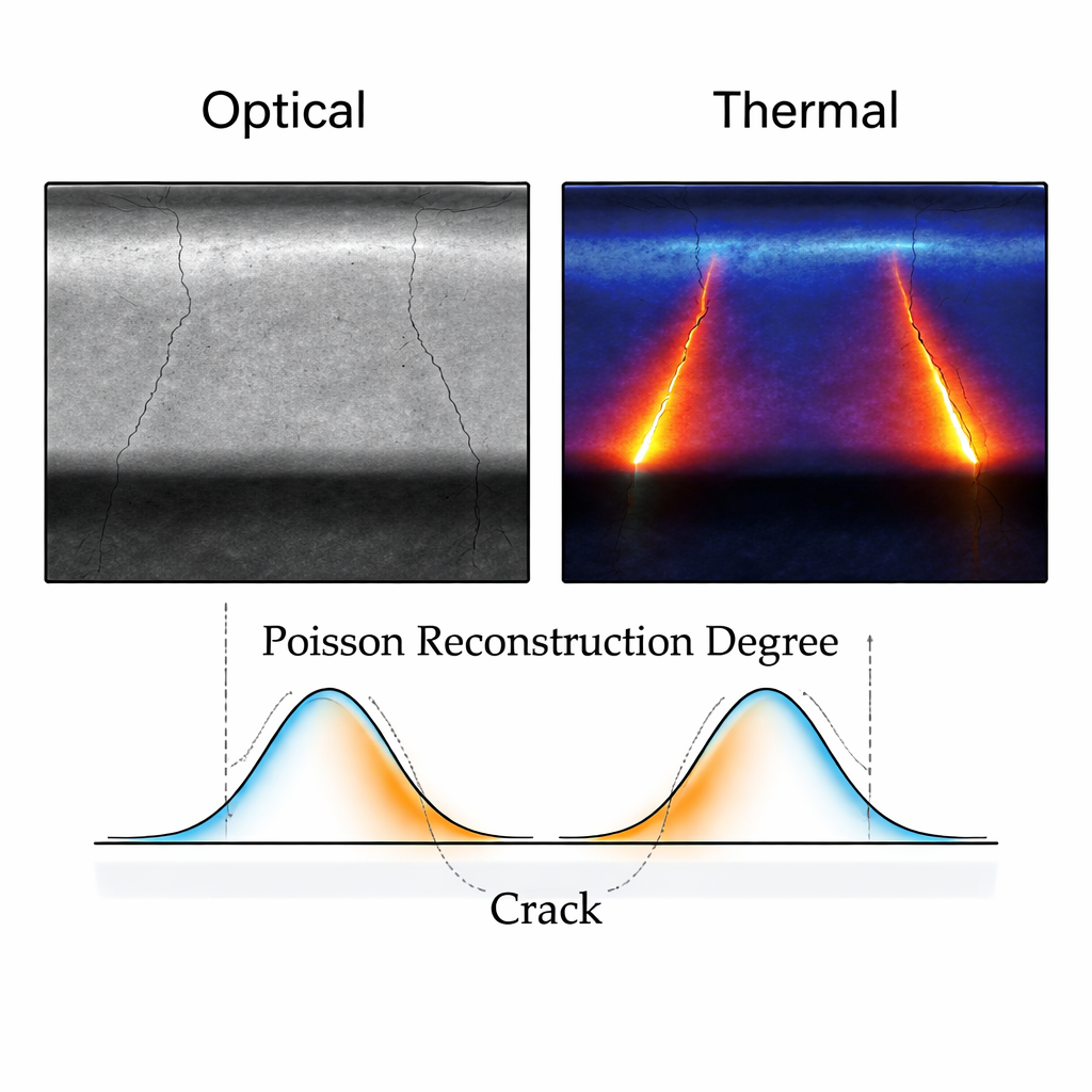
Testing on real rails, at rest and in motion
To evaluate the method under realistic conditions, the team built a rail inspection robot carrying the cameras and heating coil, and ran it over 6-meter rail samples containing wire-cut artificial cracks with carefully controlled geometries. They tested both static (rail at rest) and dynamic (robot moving) modes, and varied train-like factors such as speed and crack orientation. For cracks between fractions of a millimeter and several millimeters deep or long, the fused Poisson-based measurements showed very small errors—typically less than a few tenths of a percent in both static and dynamic tests. Importantly, the same calibrated relationships held across different crack types. Finally, the researchers examined natural rolling contact fatigue cracks cut from high-speed railway lines. Even though these real cracks were tiny and irregular, the fused images enhanced their visibility and the Poisson reconstruction degree again tracked crack depth with low error, matching independent measurements from industrial CT scans.
What this means for safer railways
For non-specialists, the key result is that the authors have turned faint image and temperature variations into a dependable “numeric fingerprint” of how big a rail crack is. By teaching a robot to see rails with both normal and thermal vision and then interpreting those images through their Poisson-based model, they can estimate crack length and depth quickly and with high precision, even while moving. This could allow inspection vehicles to cover long distances at operational speeds, catching dangerous fatigue damage earlier and reducing unnecessary rail replacements. In future work, the team plans to integrate more advanced AI algorithms and deploy the system on real high-speed lines, aiming for intelligent, real-time monitoring that quietly helps keep trains safe and on schedule beneath our feet.
Citation: Wang, Y., Miao, B., Zhang, Y. et al. Research on geometric parameter quantification of rail rolling contact fatigue crack damage based on 2D optical image. Sci Rep 16, 5715 (2026). https://doi.org/10.1038/s41598-026-36276-w
Keywords: railway safety, crack detection, thermography, machine vision, nondestructive testing