Clear Sky Science · en
Process parameter optimization for alumina ceramic parts manufactured by fused deposition modelling
Why stronger 3D‑printed parts matter
As 3D printing moves from hobbyist gadgets to real industrial components, manufacturers want parts that are not only easy to shape but also strong, heat‑resistant, and long‑lasting. Ceramics, such as alumina, are already workhorses in engines, electronics, and medical tools, yet they are notoriously hard to machine. This study explores how to reliably 3D‑print alumina parts using a common desktop‑style printer, laying out a step‑by‑step recipe that others can follow and compare, much like a standardized baking method for very demanding ingredients.
Turning a plastic printer into a ceramic tool
The researchers work with fused deposition modelling (FDM), the same basic technology used by many consumer printers that melt a plastic filament and lay it down in thin strands. Instead of plain plastic, they feed the printer a composite filament that mixes alumina ceramic powder with a removable polymer binder. After printing, the plastic must be washed and burned out, leaving a dense ceramic piece. Because tiny changes in temperature, speed, or layer thickness can make the printed object warp, crack, or lose detail, the team’s main goal is to build a structured procedure that finds reliable settings for this tricky material and documents how the parts behave.

A two‑phase recipe for better prints
The optimization is divided into two phases. In the first phase, the team focuses solely on the printing step, working with so‑called “green” parts that have not yet been chemically or thermally treated. They print simple test shapes and adjust nozzle temperature, bed temperature, print speed, layer height, wall thickness, and infill pattern through several iterations. Slowing the print speed well below that used for common plastics and choosing a moderate layer height (0.15 mm) prove crucial for consistent walls and flat bases. They also fine‑tune how far the nozzle sits above the build plate to avoid gaps or squashed layers in the bottom surface.
Tuning parts for shrinkage and heat
In the second phase, the printed pieces are taken through the full ceramic route: first a chemical bath in acetone to dissolve part of the binder, then a long, carefully controlled heat treatment in a furnace to remove the rest and sinter the alumina at about 1550 °C. These steps cause the parts to shrink by roughly one fifth in each direction and can introduce warping or cracks. To cope with this, the team systematically varies design scale factors, the number of solid bottom and top layers, the number of wall lines, and the internal infill density and pattern. From this they derive a set of scale values and structural settings that yield parts thick and robust enough to survive post‑processing without collapsing, yet not so dense that solvents or gases become trapped.
Putting the process to the test
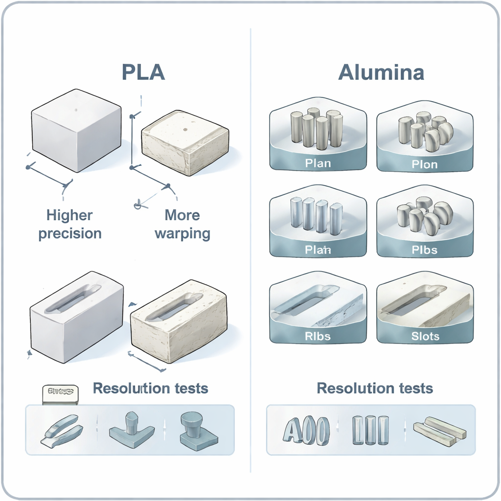
To judge how well their optimized settings work, the authors print standardized “test artifacts” defined in an international ISO standard. These shapes probe three practical qualities: overall dimensional accuracy, the smallest features the printer can still form (resolution), and surface finish, including on sloping overhangs. They make complete sets both from alumina and from a familiar plastic, PLA, using each material’s best‑known settings. Careful measurements show that alumina parts generally shrink and twist more, especially after the high‑temperature furnace stage, which harms accuracy along all three axes. Fine pins and tiny holes that are printable in PLA may either deform, disappear during the solvent and heat treatments, or fuse shut in alumina.
What this means for real‑world use
For a non‑specialist, the main takeaway is that you can, in fact, produce functional alumina ceramic parts on an FDM‑style 3D printer, but they will not yet match the precision and surface smoothness of well‑printed plastic pieces. The work provides a clear, reproducible path for dialing in temperatures, speeds, wall and infill settings, and scale corrections, and it shows where today’s limitations lie: warping during heating, loss of very small details, and rougher surfaces at steep overhangs. By formalizing this optimization workflow and pointing to the remaining weak spots in the debinding and sintering stages, the study gives industry and researchers a concrete starting point for turning low‑cost printers into more capable ceramic manufacturing tools.
Citation: Meana, V., Meana, L., Cuesta, E. et al. Process parameter optimization for alumina ceramic parts manufactured by fused deposition modelling. Sci Rep 16, 6072 (2026). https://doi.org/10.1038/s41598-026-36153-6
Keywords: ceramic 3D printing, fused deposition modeling, alumina, process optimization, additive manufacturing