Clear Sky Science · en
CFD-enabled sustainable design and manufacturing of cooling fan for unmanned helicopter
Keeping Drones Cool and Safe in the Air
As unmanned helicopters grow more capable—carrying heavier loads for longer times in hotter climates—keeping their engines cool becomes a life-or-death engineering problem. Unlike cars, these aircraft often fly with tightly sealed shells to cut drag and keep out rain, which traps heat inside. This study shows how a team of engineers used advanced computer simulations and 3D printing to redesign a key but humble part—the cooling fan—so that an unmanned helicopter can safely hover with a 500-kilogram payload even on a scorching 40 °C day, while also cutting energy use and emissions.
Why Cooling Is So Hard for Unmanned Helicopters
In a helicopter, the toughest moment for the engine is hovering. The main rotor must work hardest to hold the aircraft in place, drag forces are high, and there is little natural airflow to carry heat away. Modern unmanned helicopters add another challenge: their engine bays are carefully sealed to reduce drag and protect electronics from rain and dust. That sealed shell makes conventional radiators much less effective, because hot air cannot escape easily. As a result, the engine can quickly overheat, robbing it of power and threatening flight safety. The only practical solution is to actively force air through the radiator with a powerful fan—but that fan must fit in a cramped space, use limited electrical power, and still move a great deal of air.
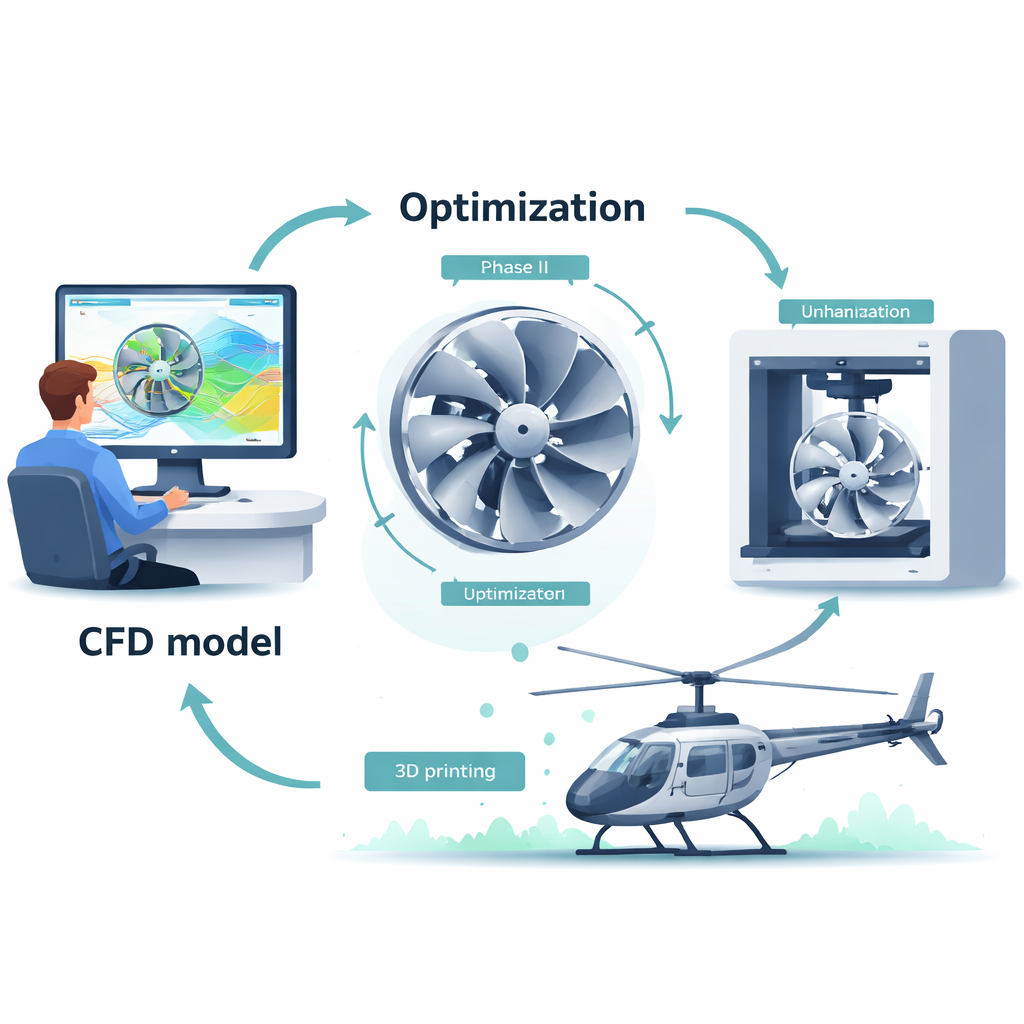
Designing a Better Fan on the Computer First
To tackle this, the researchers started with the fan already installed on their test helicopter and built a detailed digital model of how air flows through it. Using computational fluid dynamics (CFD)—software that solves the equations governing fluid motion—they recreated the fan, the inlet and outlet ducts, and the radiator’s resistance to airflow. They checked that their virtual fan matched real-world measurements and carefully tuned the mesh, or digital grid, to balance accuracy and computing cost. With this validated model, they systematically explored how four simple geometric choices affect performance: how much the blades twist from root to tip (torsion angle), how long each blade is from front to back (chord length), how steeply the blades are mounted (mounting angle), and how many blades the fan should have.
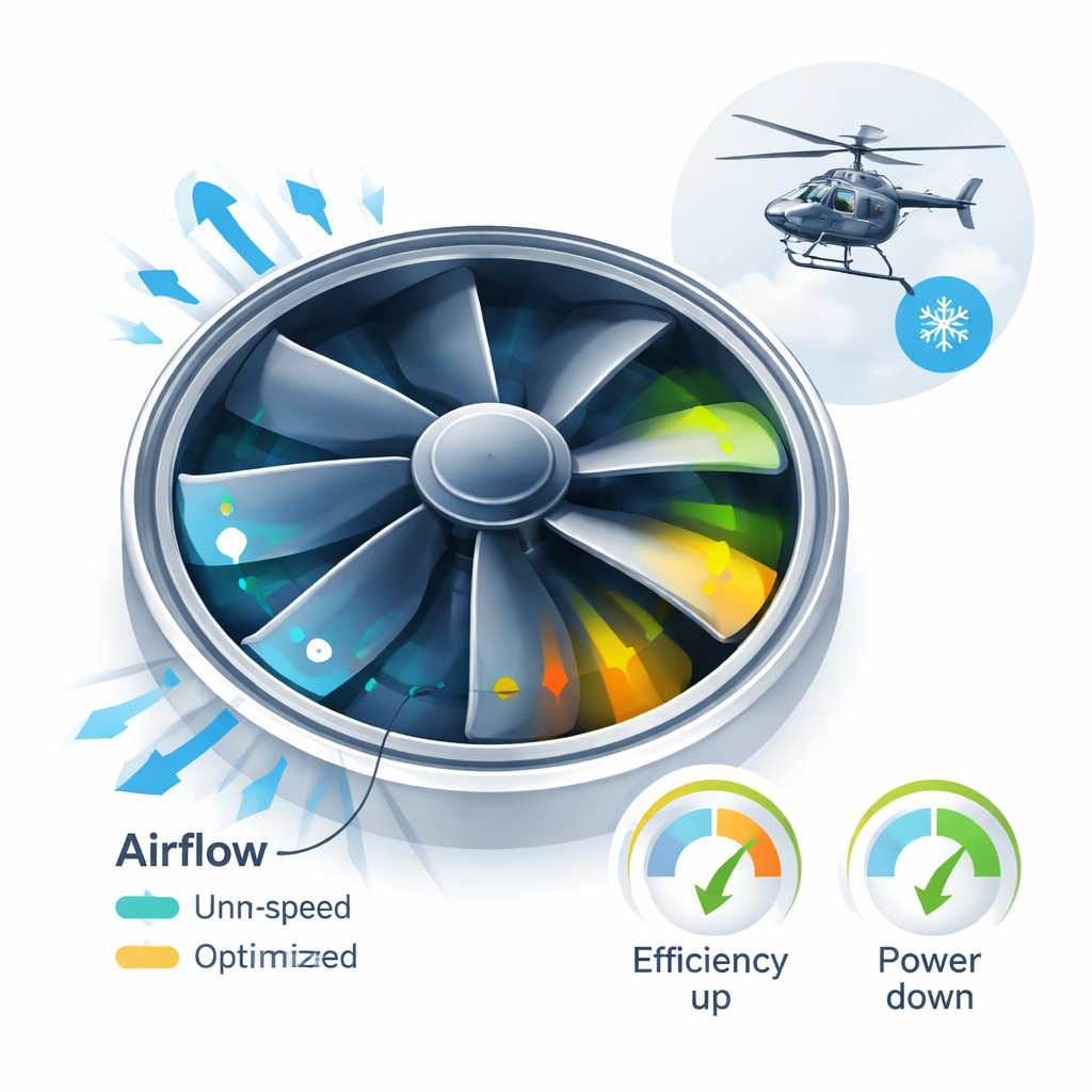
Finding the Sweet Spot for Shape and Performance
The team chose a special low-drag airfoil cross-section known as Airfoils 30, which is efficient at the relatively low air speeds found in compact cooling fans. They then ran a series of virtual experiments, changing one parameter at a time. Increasing torsion angle or making blades too long could raise static pressure but also wasted power through extra friction and swirling “backflow” near the trailing edge. Mounting the blades too flat caused weak airflow; too steep and the fan drew more than the allowed 800 watts. Adding more blades boosted pressure but also risked complex flow patterns and higher energy use. The best compromise turned out to be seven blades with a 55 mm chord length, a 26° torsion angle, and a 39° mounting angle. Compared with the original fan, this design delivered similar or higher airflow and pressure while being about 13.6% more efficient, using roughly 9.5% less power (about 73 watts), and running at 10.5% lower speed.
From Digital Blueprint to 3D-Printed Hardware
Because the optimized blades had a strong twist and precise airfoil shape, they would have been difficult and expensive to machine by traditional methods. Instead, the team sent their CFD-optimized geometry directly to a stereolithography 3D printer, building the fan in reinforced nylon with fine 0.1 mm layers and then polishing it to a smooth finish. This digital link—from simulation to printer code—meant they could produce an accurate, ready-to-test fan without multiple rounds of trial-and-error fabrication. In lab tests at 40 °C, using a full engine, radiator, and the new fan, the system maintained more than 90 kW of engine output while staying within coolant temperature limits, enough for the unmanned helicopter to hover indefinitely with a full 500 kg load.
What This Means for Flight and the Environment
For lay readers, the result can be understood this way: by carefully reshaping a fan’s blades in the computer and then “printing” that design directly, the engineers squeezed more cooling out of less power. Saving 73 watts might sound modest, but over continuous operation it translates into lower fuel burn, reduced greenhouse gas emissions—estimated at 1.2 kilograms of CO₂ per day—and a small but real increase in flight endurance. Perhaps more importantly, the same CFD-plus-3D-printing approach can be used to rapidly design other aircraft parts that are lighter, more efficient, and customized to their tasks. This work shows how digital design and sustainable manufacturing can keep unmanned helicopters safer in extreme conditions while supporting the broader push toward greener aviation.
Citation: Si, L., Liu, Z., Xiao, N. et al. CFD-enabled sustainable design and manufacturing of cooling fan for unmanned helicopter. Sci Rep 16, 5603 (2026). https://doi.org/10.1038/s41598-026-35901-y
Keywords: unmanned helicopter cooling, CFD fan design, additive manufacturing, aerospace sustainability, radiator airflow