Clear Sky Science · en
Performance evaluation of a series-connected step-up/down partial power converter for battery energy storage applications
Why smarter battery chargers matter
As homes, cars, and data centers lean more heavily on big battery packs, even small improvements in the electronics that charge and discharge those batteries can save money and energy. Traditional circuits that connect a battery to a direct‑current (DC) grid must handle all of the power all of the time, making them bulky and wasteful. This paper explores a new kind of "partial" power converter that lets most of the energy bypass the converter altogether, cutting losses and shrinking hardware—while still keeping tight control over how the battery is charged and discharged.
A new way to route battery power
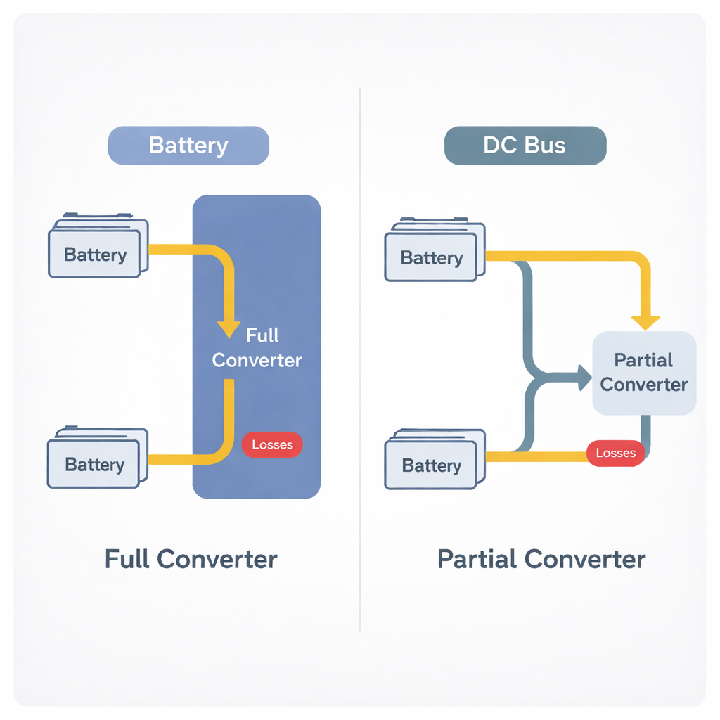
In a conventional full power converter, every watt flowing between a battery and a DC bus must pass through the converter hardware. That means the switches, coils, and capacitors are sized for the full system power, and they all heat up whenever energy moves in or out of the battery. The authors instead focus on a partial power converter that is wired in series with the battery. In this arrangement, most of the power travels directly between the battery and the DC bus along a low‑loss path, while only a small portion passes through the converter, which adds or subtracts a “trim” voltage on top of the battery voltage. Because the converter sees only a fraction of the total power, its components can be smaller and more efficient.
Making step‑up and step‑down work in one box
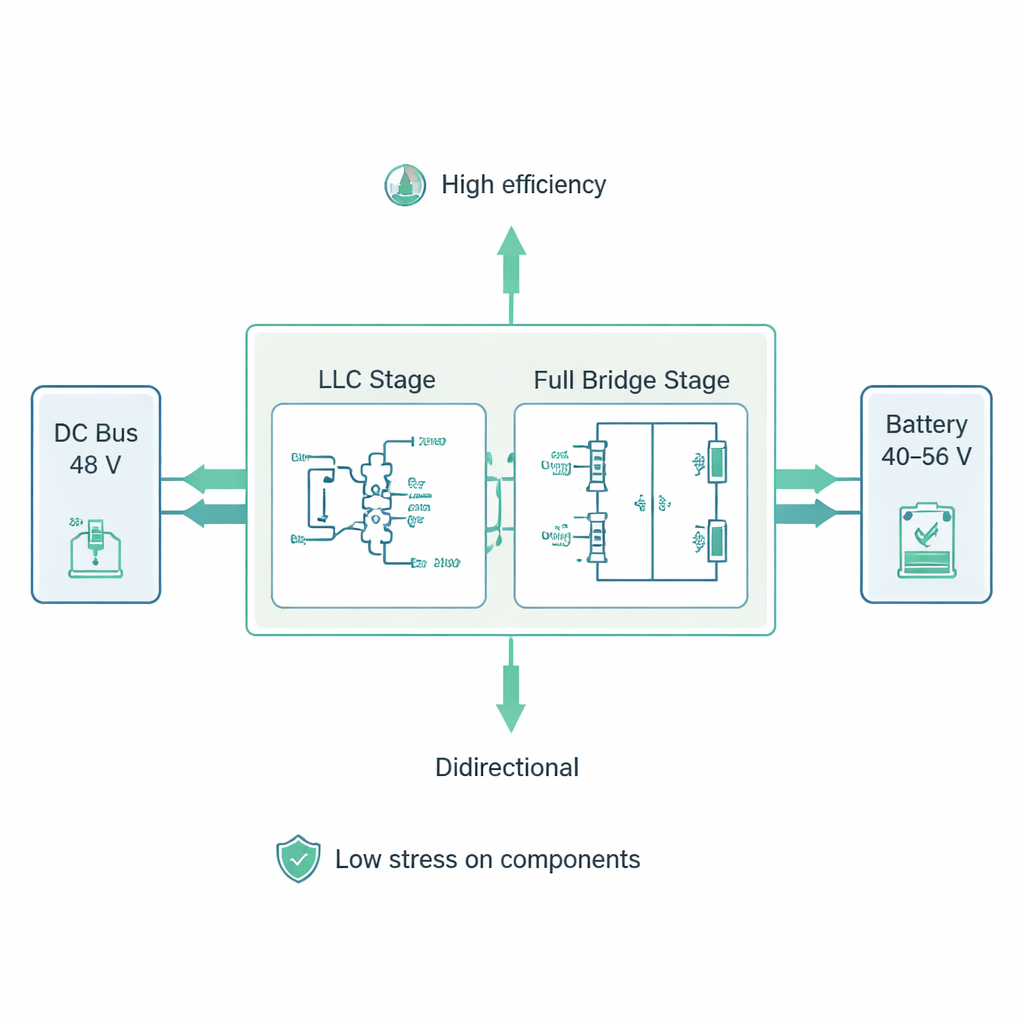
Real battery systems must both raise and lower their voltage as the battery’s state of charge and the grid conditions change. Many earlier partial power designs handled only one direction well: either boosting or reducing voltage. The team proposes a step‑up/down partial power converter that can smoothly cover both cases. It combines two building blocks inside one box: an LLC resonant stage that acts as a highly efficient, isolated "DC transformer," and a full‑bridge stage that finely adjusts the series voltage seen by the battery. By carefully choosing the transformer ratio and switching patterns, the converter can generate a small positive or negative offset voltage, so it can help either charge or discharge the battery over its full 40–56 V range while keeping the main DC bus at 48 V.
Judging performance by what components feel
Simply counting how much active power passes through the converter does not tell the whole story. Internal energy sloshing back and forth in inductors and capacitors—called nonactive power—still heats components and wastes energy. The authors therefore evaluate both active and nonactive power, and define a "component stress factor" that combines voltage and current stress into a single figure of merit. Using circuit simulations, they compare their new topology with a standard four‑switch buck‑boost converter that processes full power, and with a previously studied partial power design based on a phase‑shifted full bridge. For the same battery and bus voltages, the new step‑up/down partial converter shows the lowest circulating energy and the lowest overall stress on its switches, coils, and capacitors.
From design rules to real hardware
To make the approach usable in practice, the paper lays out general connection rules for when and how to place partial converters in series with batteries, depending on whether the system mainly needs to step voltage up, step it down, or do both. It also provides a step‑by‑step sizing method for the transformer, inductors, capacitors, and power switches so that the circuit maintains soft switching and low ripple over the full operating range. The authors then build a 1.1 kilowatt laboratory prototype controlled by a digital signal processor and test it with a realistic 50 amp‑hour lithium‑ion battery model. Measurements during both charging and discharging show that, at full load, only about 14.3% of the total power actually flows through the converter hardware; the rest goes directly between the DC bus and the battery.
What this means for future battery systems
For a non‑specialist, the core result is that by letting most of the energy take a "shortcut" around the converter and forcing only a small corrective portion through the electronics, the system becomes both smaller and more efficient. The prototype achieves a peak efficiency of about 98.15%, and an average efficiency of 98.6% over a full charge cycle—higher than comparable full‑power and earlier partial‑power designs. This suggests that future home storage units, electric‑vehicle chargers, and data‑center backup systems could deliver the same power with less hardware, lower heat, and potentially lower cost by adopting carefully designed step‑up/down partial power converters.
Citation: Liu, Q., Jing, L., Xu, W. et al. Performance evaluation of a series-connected step-up/down partial power converter for battery energy storage applications. Sci Rep 16, 5577 (2026). https://doi.org/10.1038/s41598-026-35857-z
Keywords: battery energy storage, power converter, partial power processing, high efficiency charging, DC microgrid