Clear Sky Science · en
Discrete thermal analysis of the E–type shell–and–tube heat exchanger
Why this matters for everyday energy systems
From power plants and ships to chemical plants and data centers, heat exchangers quietly move heat from one place to another, making modern life possible. Yet engineers still struggle to predict exactly how heat and temperature change inside these devices when flows become complicated. This paper presents a new numerical way to "look inside" one of the most common industrial heat exchangers and build detailed temperature and heat maps that can guide safer, more efficient designs.
What a shell-and-tube heat exchanger looks like
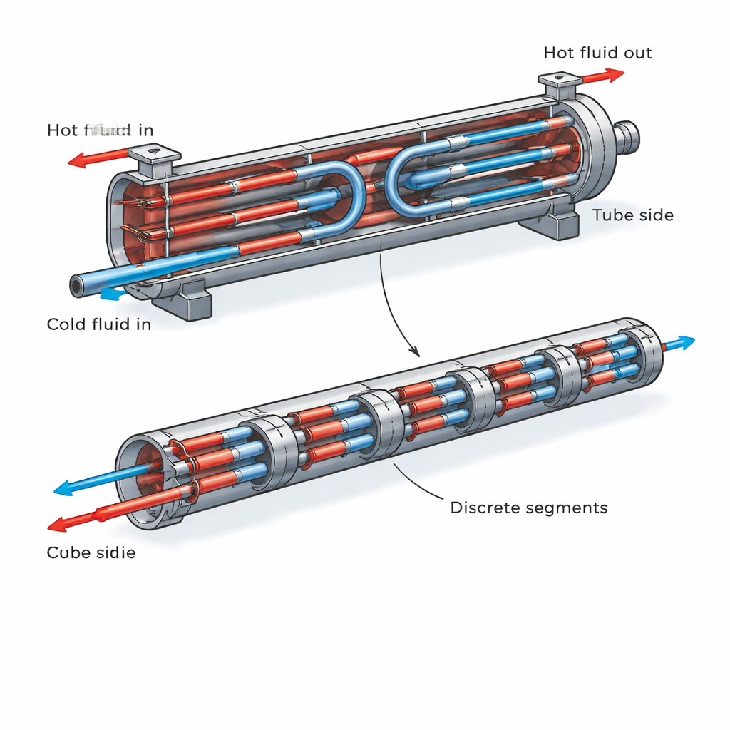
The study focuses on E-type shell-and-tube heat exchangers, a workhorse design found in many industries. In these units, one fluid flows through bundles of metal tubes while another fluid flows around them inside a larger shell. The fluids may be water, oil, refrigerants, or process streams, and they can carry huge amounts of heat. Engineers usually describe performance with compact formulas that treat the exchanger almost like a black box, using averages rather than local details. Those traditional methods work well for simple, smooth temperature changes but can fall short when flows reverse, when properties vary strongly with temperature, or when designers need to know exactly where thermal stresses or critical “pinch” regions occur.
A new way to slice the problem into smaller pieces
The authors adapt and extend a technique called the Discrete Sub–Heat Exchanger (DSHE) method. Instead of treating the heat exchanger as a single unit, they divide it into many small pieces lined up along its length. Each piece behaves like a tiny, simple heat exchanger with either parallel or counter-flow between the two fluids. By applying well-known effectiveness–NTU formulas to every tiny piece and updating temperatures step by step, the method builds up a full picture of how temperatures and heat flow change from inlet to outlet on both the tube side and the shell side. This is done under fixed values of two key dimensionless parameters: NTU, which roughly measures how much heat transfer area is available, and the heat-capacity ratio, which compares how easily each fluid can change temperature.
Seeing temperature crossings and reverse heat flow
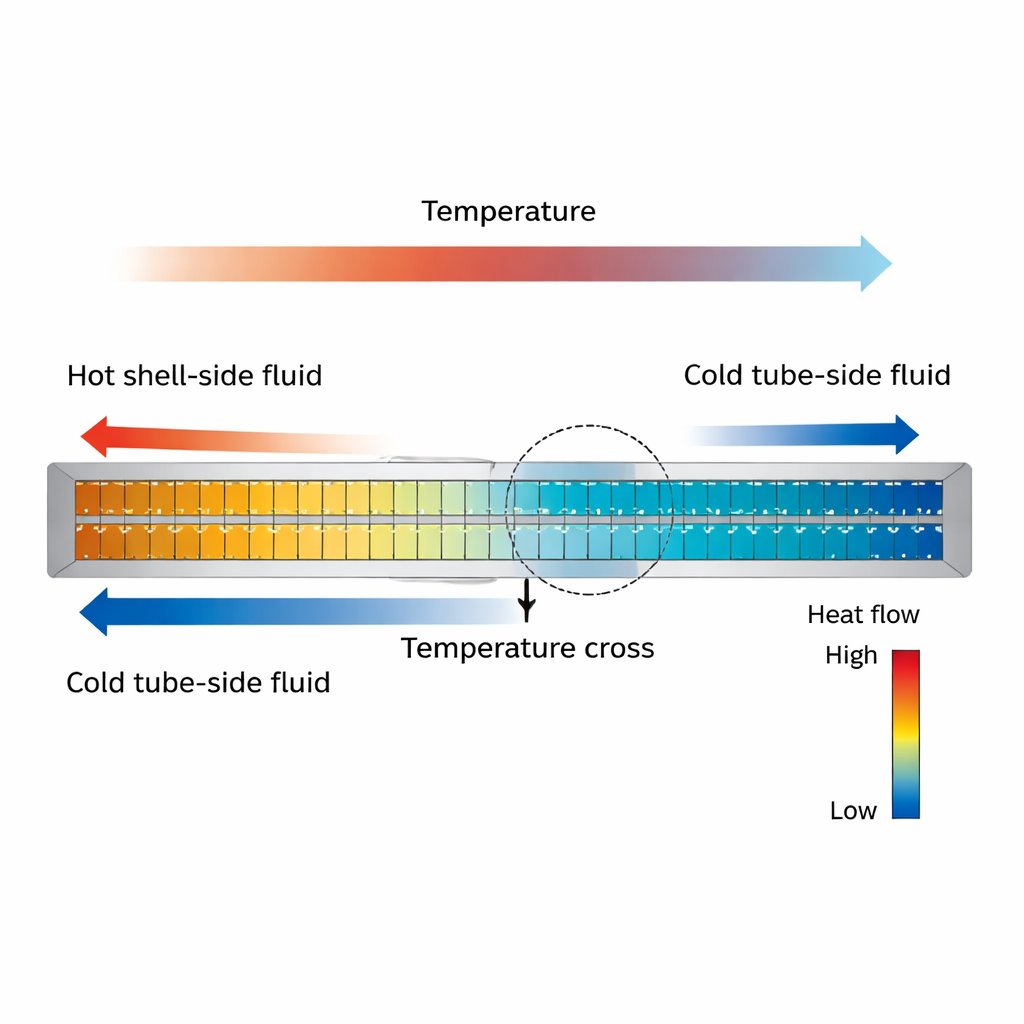
To test the DSHE method, the researchers simulate two real-world design cases from the literature. In the first case, temperature changes are modest and the hot fluid stays hotter than the cold fluid everywhere, a relatively gentle situation. In the second, the exchanger is stronger (higher NTU) and the cold fluid is warmed so much that, at some point along the length, it actually becomes hotter than the shell-side fluid. This “temperature cross” leads to sections where part of the flow sees reverse heat transfer relative to the rest of the device. The DSHE method captures this behavior clearly, producing one-dimensional temperature profiles, colorful temperature maps, and heat-transfer maps that highlight where heat flows forward, where it weakens, and where it briefly reverses.
How accurate and efficient is the new method?
Because the DSHE model is numerical, the authors carefully check its reliability. They compare its predicted overall effectiveness (how much of the maximum possible heat transfer is achieved) to known analytical formulas for the same exchanger type. For both test cases, the differences are extremely small, often in the range of one part in a million or better. They show that increasing the number of discrete pieces makes the results smoother and more accurate, but also increases computing time. By running systematic “sensitivity” studies, they map how numerical error grows with NTU and with the fluid heat-capacity ratio, and how it shrinks when more segments are used. They also identify a practical convergence check based on the first law of thermodynamics: the numerical solution is accepted only when the total heat gained by one fluid matches, within a very tight tolerance, the heat lost by the other.
What this means for design and operation
For non-specialists, the main message is that this method turns a complex heat exchanger from an opaque box into a transparent one. Designers can now generate detailed internal temperature and heat-flow maps without having to derive new analytic formulas for every flow arrangement. That means they can better spot dangerous hot or cold spots, locate regions where thermal stresses may threaten mechanical integrity, and identify where to add enhancements to boost performance. The work lays the groundwork for applying the same discrete approach to even more complicated exchangers and to challenging conditions such as two-phase or supercritical flows, supporting more efficient and reliable energy systems.
Citation: Bayramoğlu, K., Kaya, I. & Ust, Y. Discrete thermal analysis of the E–type shell–and–tube heat exchanger. Sci Rep 16, 5281 (2026). https://doi.org/10.1038/s41598-026-35215-z
Keywords: heat exchangers, shell-and-tube, thermal modeling, numerical simulation, temperature profiles