Clear Sky Science · en
Design of a Low-Loss microstrip Lowpass-Bandpass triplexer with closely spaced channels for modern RF communication systems
Why splitting radio signals matters
Every time your phone, a smart sensor, or a wireless charger talks over the air, a jumble of different radio signals must share the same tiny piece of hardware. Engineers need ways to neatly sort these signals by frequency so that a device can listen, talk, and even harvest stray energy at once without the channels interfering. This paper introduces a very compact radio-frequency (RF) circuit, called a lowpass-bandpass triplexer, that can do exactly that for three closely spaced frequency bands used in modern communication and energy-harvesting systems.
A three-lane highway for wireless signals
The authors design a microstrip triplexer, a flat circuit etched on a thin board, that splits signals coming from one common port into three frequency lanes. One lane is a lowpass path that passes all signals up to about 1.02 GHz, while the other two are bandpass paths centered at 1.6 GHz and 2.35 GHz. These bands lie in the popular mid-frequency spectrum used by 5G networks and wireless power systems. What makes the work notable is that the three channels sit unusually close together in frequency, yet the circuit still keeps signal leakage and loss extremely low, all within a footprint of only about 0.02 of a square guided wavelength—very small by RF standards. 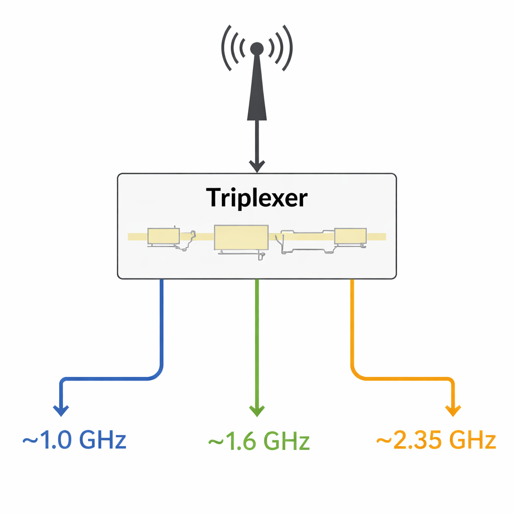
Building blocks behind the tiny circuit
To achieve this, the researchers start from a simple but carefully chosen building block: a lowpass filter made from a narrow transmission line periodically loaded with small metal “patch cells.” They describe this structure with an equivalent circuit made of inductors and capacitors, which lets them write equations for the filter’s cutoff frequency. By adjusting the patch capacitances upward, they can shrink the required inductive line lengths, effectively miniaturizing the layout while keeping the cutoff fixed near 1.02 GHz. Because the analysis also suppresses unwanted harmonics—spurious passbands at higher frequencies—the lowpass section provides a clean foundation for additional channels.
Adding tuned side branches for extra bands
The second and third channels are created by attaching resonant side branches, or bandpass resonators, to the lowpass line. Each resonator behaves like a tuned circuit that strongly passes only a narrow slice of frequencies—around 1.6 GHz for the first and 2.35 GHz for the second—while appearing “invisible” to other frequencies. The authors again derive a simplified circuit model, showing that increasing the resonator capacitance lets them shorten the inductive line sections without shifting the target frequency, which helps keep the whole device small. Two such resonator-equipped sections are first realized as separate two-channel circuits called diplexers and then combined to form the final three-channel triplexer without using additional ground vias, which could introduce unwanted parasitic effects.
Fine-tuning performance through simulation and measurement
Using commercial electromagnetic simulation software, the team optimizes a handful of key line lengths to balance three competing goals: low loss, strong separation between channels, and compact size. Small changes in these dimensions can shift passbands or weaken them, and the authors map out how each parameter affects the response. They then fabricate the circuit on a low-loss substrate and measure its behavior using a precision vector network analyzer. The measured insertion losses—how much signal is absorbed or reflected instead of forwarded—are just 0.4 dB, 0.19 dB, and 0.11 dB in the three channels, with reflections at each port kept below −18 dB, meaning almost all of the incoming power is delivered where it should go. Harmful signal leakage between any pair of outputs remains better than about −19 dB across the operating range. 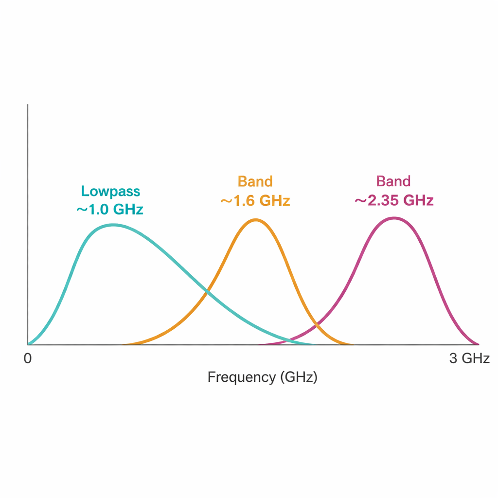
What this means for future wireless devices
In plain terms, the proposed triplexer acts like an exceptionally tidy three-way splitter that can separate tightly packed radio channels with very little wasted energy and in a very small area. Compared with earlier designs, it offers much lower loss, better matching, and a smaller footprint, all while handling closer channel spacing. This combination makes it attractive for crowded RF front-ends in 5G base stations, Internet-of-Things nodes, and wireless energy-harvesting circuits, where space is limited but efficiency and signal quality are critical. The design approach—using clear circuit models to guide miniaturization and then refining with careful optimization—also provides a roadmap for engineers who want to pack even more frequency channels into tomorrow’s compact wireless hardware.
Citation: Yahya, S.I., Zubir, F., Nouri, L. et al. Design of a Low-Loss microstrip Lowpass-Bandpass triplexer with closely spaced channels for modern RF communication systems. Sci Rep 16, 4886 (2026). https://doi.org/10.1038/s41598-026-35043-1
Keywords: microstrip triplexer, lowpass-bandpass filter, 5G RF front-end, multi-band wireless, wireless energy harvesting