Clear Sky Science · en
Phase error analysis for MEMS gyroscopes operational modes based on force-to-rebalance rate measurement mode
Why tiny gyroscopes matter
From stabilizing drones to guiding autonomous cars, tiny motion sensors known as MEMS gyroscopes quietly keep modern devices balanced and on course. To measure rotation accurately, these chips depend on carefully timed electronic control loops. This paper explores how subtle timing mismatches—called phase errors—inside these loops can degrade performance, and shows which of these errors really matter and how to correct them so that gyroscopes stay precise and trustworthy.
Two vibrations that feel rotation
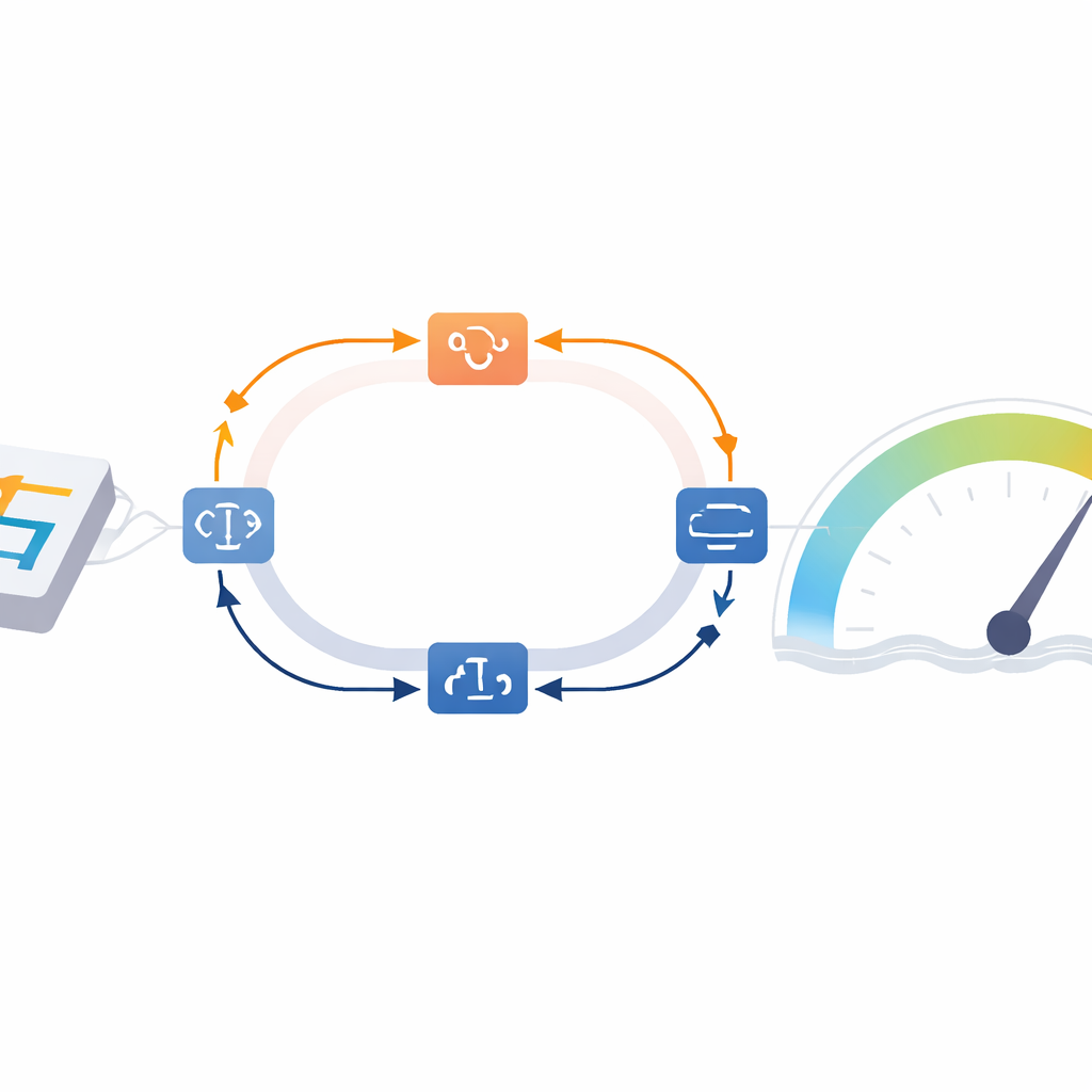
A MEMS gyroscope works by vibrating a small silicon structure in two perpendicular directions: a drive mode that is actively shaken, and a sense mode that feels the sideways push created when the device rotates. Electronics keep the drive vibration steady and convert the tiny motion of the sense mode into a rate reading. In many advanced gyroscopes, a method called force-to-rebalance (FTR) is used: instead of letting the sense structure move freely, the electronics push back just enough to cancel its motion. The amount of corrective force then reveals the rotation rate. This approach is prized for its stability, but relies heavily on precise timing between signals.
Where timing slips into error
In real devices, signals must pass through analog circuits that turn changing capacitance into voltage, digital processing inside an FPGA chip, and data converters that bridge the analog and digital worlds. Each of these steps can shift the phase, or timing, of the signals by a tiny angle. The authors group these phase errors into two simple categories in each vibration path: those that occur while measuring and processing signals (the feedback path) and those that occur while generating actuation signals (the forward path. They then build a full mathematical model of the FTR control loops, including both paths in both modes, and analyze how such errors influence key performance measures like bias, scale factor, bandwidth, and the ability to cancel unwanted coupling, known as quadrature error.
Probing the drive side: mostly harmless
On the drive side, phase errors cause the control loop to lock slightly away from the structure’s true natural frequency. To keep the vibration level constant, the electronics respond by increasing the drive amplitude. Intuitively, this might be worrisome, because a stronger drive can leak into the sense path as electrical feedthrough. However, the gyroscope studied here uses a carefully designed front-end circuit with a high-frequency carrier and ring diodes that largely suppress this leakage. Simulations and detailed experiments under three temperatures show that, once the device has warmed up, the drive-loop phase errors settle to nearly constant values and, after simple calibration, have negligible impact on bias, noise, quadrature correction, or FTR bandwidth.
Sense side timing: the real troublemaker
The sense mode tells a different story. Here, the feedback signal that pushes back on the vibrating mass and the reference signals used to extract the rate and quadrature components must be in tight alignment. The authors derive an FTR loop model that explicitly includes a phase error in the sense feedback path and another in the forward demodulation path. They show analytically and then experimentally that the feedback-path phase error directly changes the scale factor—the conversion between true rotation and measured output—and worsens the zero-rate output, which should ideally be perfectly stable when the gyroscope is at rest. In contrast, the forward-path phase error has only a minor influence on these static characteristics, and both sense-side errors have little effect on dynamic bandwidth.
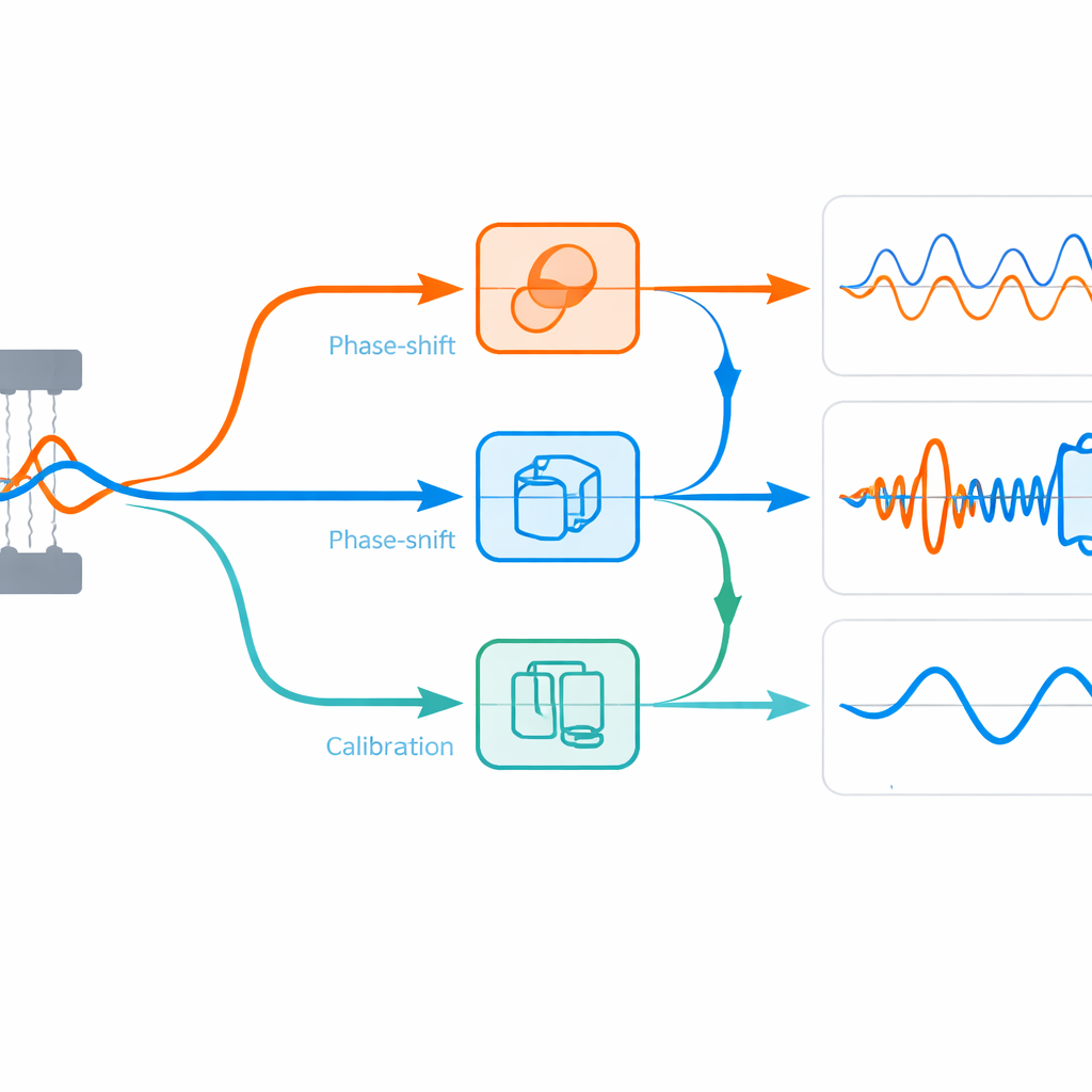
Calibrating what matters most
Building on these insights, the team proposes practical calibration procedures. For the drive mode, they measure phase differences between internal reference waves and the actual drive signal, then adjust digital phases until the signals become orthogonal and the drive amplitude drops to a minimum, revealing and canceling both forward and feedback phase errors. For the sense mode, they first align the feedback signal with a reference to fix the critical feedback-path error. Then they deliberately boost the quadrature signal so that its phase dominates, making it easy to fine-tune the remaining forward-path phase. Tests across temperatures show that these corrections behave like constant offsets that must be re-estimated when conditions change, but once set, they greatly stabilize scale factor and bias.
What this means for future sensors
In plain terms, this study shows that not all timing errors in a MEMS gyroscope are equally important. With feedthrough carefully suppressed, phase errors in the drive loop and in the sense forward path have little effect on the final rotation reading. The dominant culprit is the phase error in the sense feedback path, which directly bends the “ruler” used to measure rotation and shifts the reading at rest. By pinpointing this weak link and offering targeted calibration strategies, the work provides a roadmap for designing gyroscopes with better in-run stability and paves the way for real-time compensation schemes that can maintain accuracy even as temperature and other conditions vary.
Citation: Jia, J., Zhang, H., Gao, S. et al. Phase error analysis for MEMS gyroscopes operational modes based on force-to-rebalance rate measurement mode. Microsyst Nanoeng 12, 86 (2026). https://doi.org/10.1038/s41378-025-01144-6
Keywords: MEMS gyroscope, force-to-rebalance control, phase error, sensor calibration, inertial navigation